4-6 E6198B Switch/Load Unit User Manual
4 Configuring the Switch/Load Unit
Configuring the Power Busses
The UUT power supplies attach to the power busses PB1-PB4.
Figure 4-4 shows the power bus connectors J801 and J802
located on the Switch/Load Unit backplane PC board for system
integrated SLU. These connectors use screw terminations for
high current capability. The J801 connectors are bussed
together on the PC board providing a common connection for up
to three supplies.
The following examples A and B show the two most common
ways of configuring the power busses.
Example A shows three separate supplies attached to the
busses, with all three sharing a common ground on Power Bus 1
(PB1). This is the factory default configuration. The grounds for
all three supplies are connected together on connector J801.
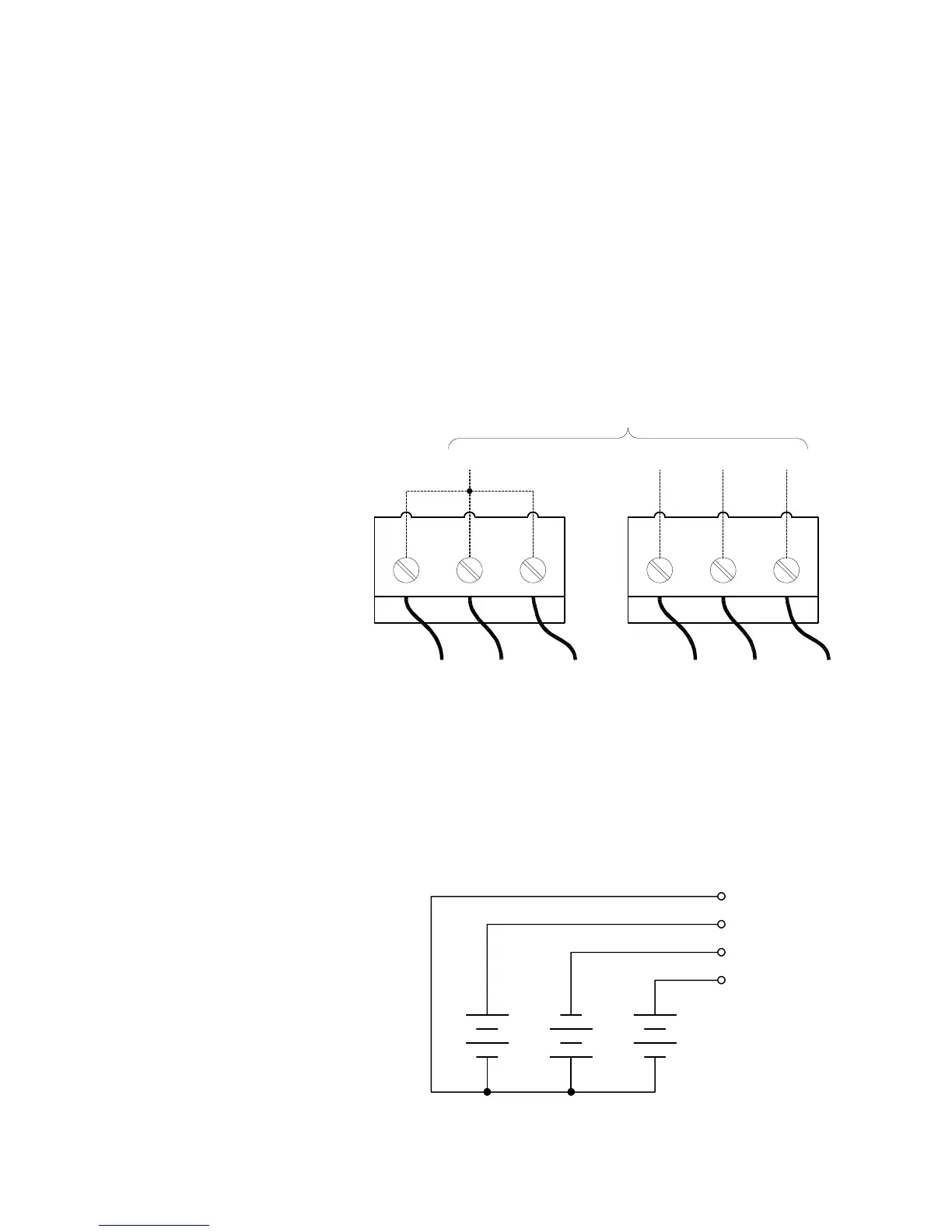
Figure 4-4 Power Bus Connectors J801 and J802
Figure 4-5 Example A: Three Separate Supplies on PB1 - PB4
J801 J802
PB1 PB2 PB3 PB4
PC Board Traces