Using Load Cards and Loads 5
E6198B Switch/Load Unit User Manual 5-21
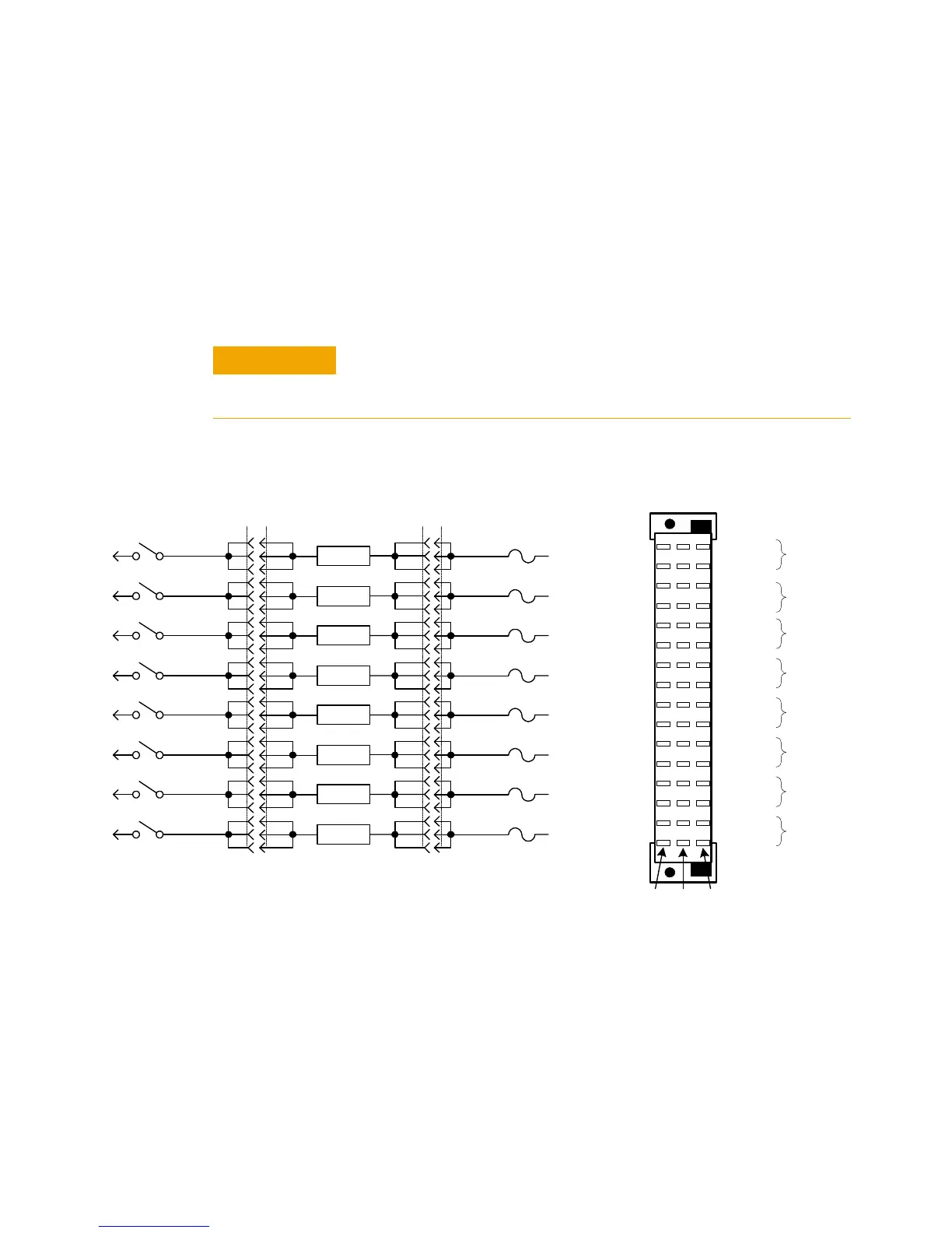
Load Wiring
Figure 5-14 is a simplified schematic and P1 connector pinout
showing how loads are connected to P1. Load 1 connects to
Channel 1 (P1 row 16) and Power 1 (P1 row 15); Load 2
connects to Channel 2 (P1 row 14) and Power 2 (P1 row 13), and
so on.
To prevent premature pin failure from excessive current flow, when
connecting high-current (>3 amp) loads to P1, wire across all three
pins in each row (see Figure 5-15 on page 22).
Figure 5-14 Agilent E6175A Load Wiring Schematic and P1 Pinouts
Row 16
A
CE
P1 Connector
(Wiring Terminal View)
Row 15
Row 14
Row 13
Row 12
Row 11
Row 10
Row 9
Row 8
Row 7
Row 6
Row 5
Row 4
Row 3
Row 2
Row 1
Channel 1
Power 1
Channel 2
Channel 3
Channel 4
Channel 5
Channel 6
Channel 7
Channel 8
Power 2
Power 3
Power 4
Power 5
Power 6
Power 7
Power 8
Load 1
Load 2
Load 3
Load 4
Load 5
Load 6
Load 7
Load 8
Load 1
Power 1
15 A
15 C
15 E
Load 2
Power 2
13 A
13 C
13 E
Load 3
Power 3
11 A
11 C
11 E
Load 4
Power 4
9 A
9 C
9 E
Load 5
Power 5
7 A
7 C
7 E
Load 6
Power 6
5 A
5 C
5 E
Load 7
Power 7
3 A
3 C
3 E
Load 8
Power 8
1 A
1 C
1 E
J1P1
Odd # RowsEven # Rows
J1
16 C
16 A
16 E
Channel 1
14 C
14 A
14 E
Channel 2
12 C
12 A
12 E
Channel 3
10 C
10 A
10 E
Channel 4
8 C
8 A
8 E
Channel 5
6 C
6 A
6 E
Channel 6
4 C
4 A
4 E
Channel 7
2 C
2 A
2 E
Channel 8
P1