5-20 E6198B Switch/Load Unit User Manual
5 Using Load Cards and Loads
Bridge load flyback protection may be installed to power busses
as a normal load if jumpered, or channel to channel by installing
protection devices across the bridged channels.
Connecting Loads
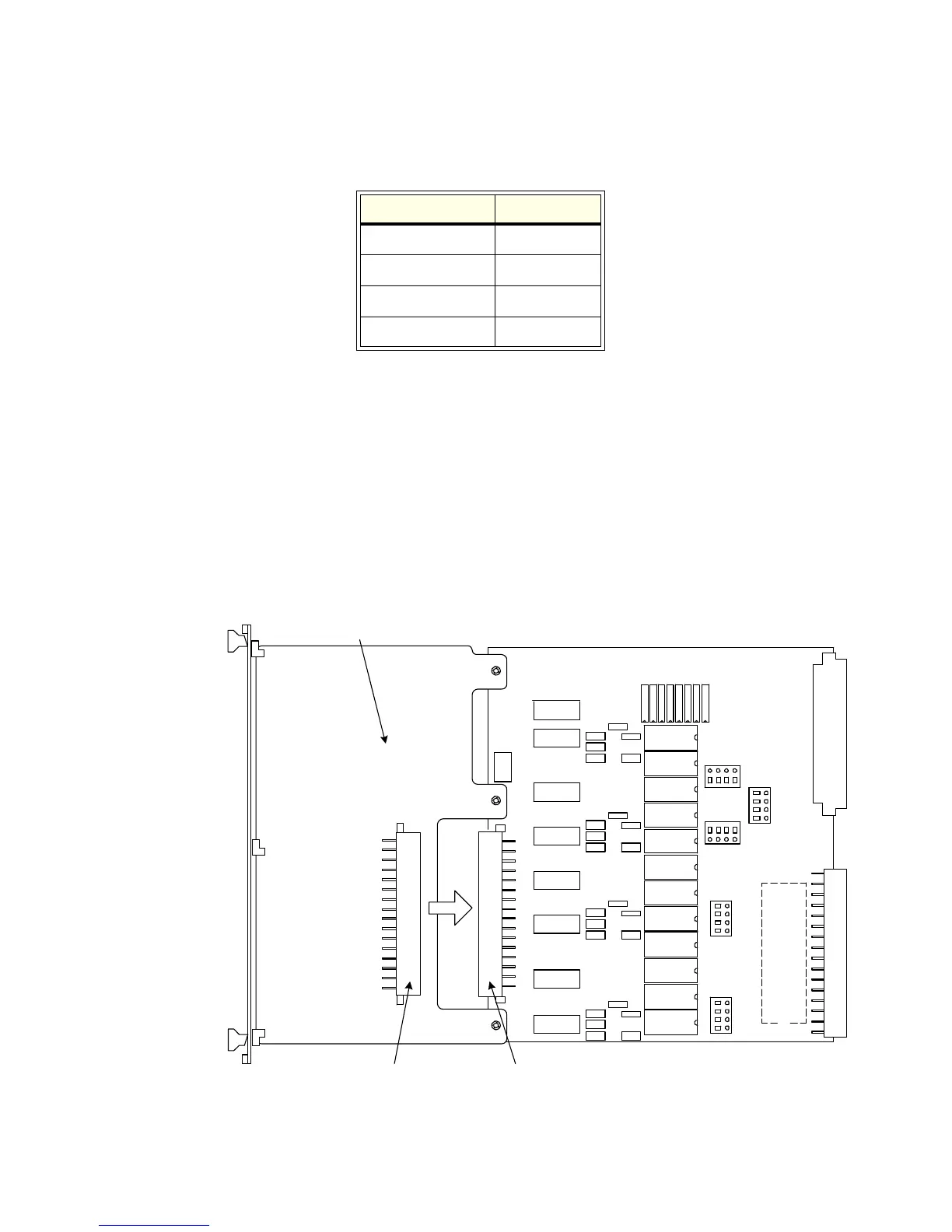
Loads are mounted on the Agilent E6175A’s sheet-metal
mounting area. The loads are wired to connector P1 which
mates to the Agilent E6175A’s J1 connector. Figure 5-13 shows
the Agilent E6175A’s load mounting area and connectors J1 and
P1.
Bridge Circuit on: Jumper Pins:
Channels 1 and 2 J6, 1 and 2
Channels 3 and 4 J6, 3 and 4
Channels 5 and 6 J7, 1 and 2
Channels 7 and 8 J7, 3 and 4
Figure 5-13 Agilent E6175A Load Mounting Area and P1/J1 Connectors