5-22 E6198B Switch/Load Unit User Manual
5 Using Load Cards and Loads
Current Sharing
Notice in the wiring schematic (Figure 5-14) that pins A, C and
E in each row of J1 are connected together on the PC board.
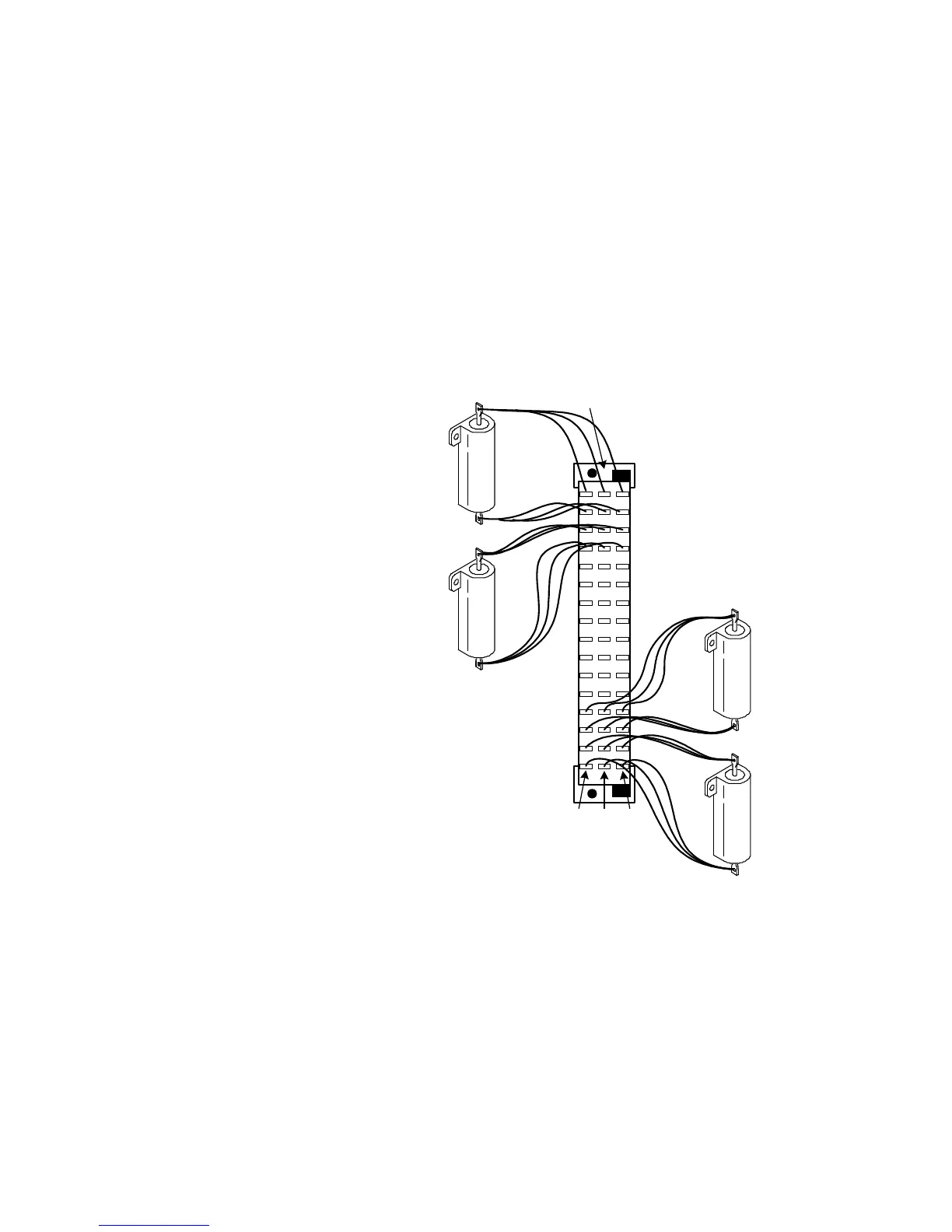
When connecting high-current (>3 amp) loads, wire across all
three pins in each row of P1 (see Figure 5-15). This ensures
current sharing across all pins and prevents premature pin
failure from excessive current flow.
Figure 5-15 Agilent E6175A Current Sharing Example
Row 1
Row 16
ACE
Load 1
Load 2
Load 7
Load 8
P1 Connector
(Wiring Terminal View)