Using the Pin Matrix Cards 6
E6198B Switch/Load Unit User Manual 6-11
J1 Instrument Connections
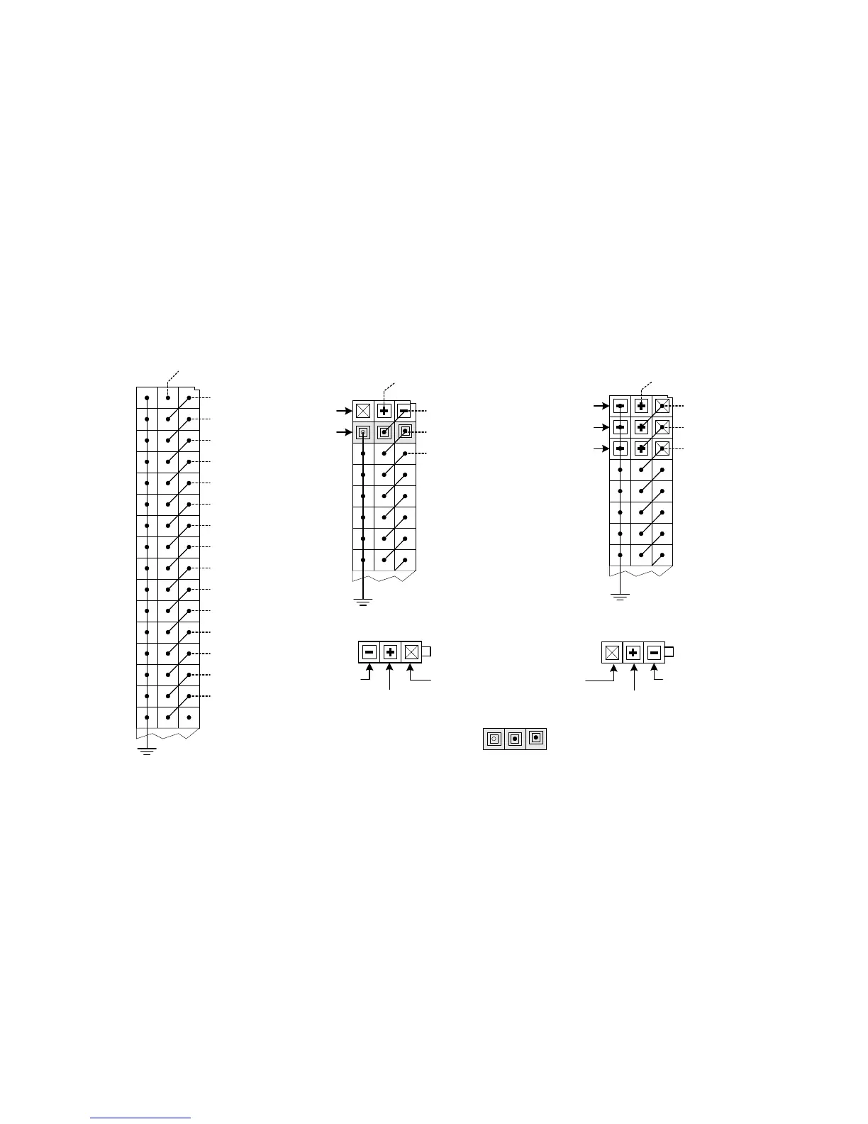
Figure 6-6 shows where instrument connections can be made on
the J1 Connector. Notice, for example, that the INST2
connection is located in Row 32, Column C and is also
connected to Row 31, Column B. This arrangement lets you
make either floating or earth-referenced connections as shown
in Figure 6-6.
Figure 6-6 J1 Example Instrument Connections
Agilent E3750-61621/E6170-61612
"Floating Instruments"
Agilent E3750-61604 /E6170-61614
"Single Ended Instruments"
No
Connection
Signal
Drain
Signal
Low
No
Connection
INST2
INST3
INST1
INST4
INST5
INST6
INST7
INST8
INST9
INST10
INST11
INST12
INST13
INST14
INST15
INST16
J1 INST Connections
J1 Earth-Referenced Connections
(no filler plugs needed)
Cable INST2
INST3
INST1
Cable
Cable INST4
J1 Floating Connections
INST1 = +, INST2 =
−
(use filler plugs on each side of cable)
Cable INST2
INST3Filler
INST4
INST1
32
31
18
17
24
26
22
23
21
25
19
20
27
28
29
30
Agilent 1252-4353 Filler Plug

 Loading...


