Using Load Cards and Loads 5
E6198B Switch/Load Unit User Manual 5-19
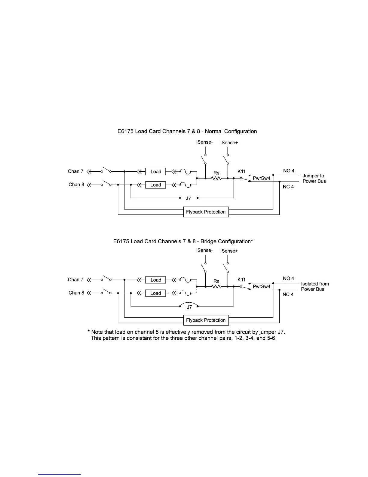
Setting up a Bridge Configuration
In the bridge configuration the power bus power supplies are
not used. The power for the bridge is supplied by the module;
the connection to the UUT power supply is effectively bypassed.
See Figure 5-12.
Use the following table to determine the appropriate pins on J6
and J7 to jumper to create a bridge circuit on the indicated
channels.
Figure 5-12 Bridge Configuration for Channels 7 and 8 on 8-Channel Load Card