5-32 E6198B Switch/Load Unit User Manual
5 Using Load Cards and Loads
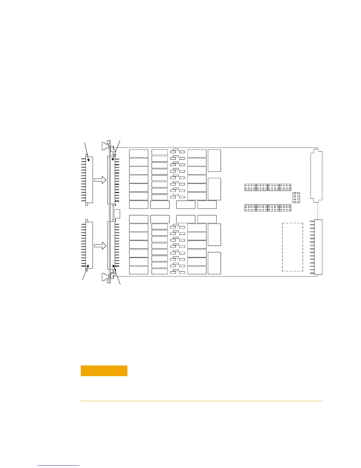
Connecting Loads
Loads are mounted externally and connected to the load card
via wires or cables. The loads are wired to connectors P1 and P2
which mate to the Agilent E6176A’s J1 and J2 connectors,
respectively. Figure 5-13 shows these connectors.
Load Wiring
Figure 5-23 is a simplified schematic and connector pinouts
showing how loads are connected to P1/P2. Loads 1 through 8
connect to P1 and loads 9 through 16 connect to P2.
Figure 5-22 Agilent E6176A Connectors J1/J2 and Mating Connectors P1/P2
J1
Mating
Connector
for J1
J2
Mating
Connector
for J2
To prevent premature pin failure from excessive current flow,
when connecting high-current (>3 amp) loads to P1, wire
across all three pins in each row (see Figure 5-24 on page
34).