6-16 E6198B Switch/Load Unit User Manual
6 Using the Pin Matrix Cards
Using the 64-Pin Matrix Cards
Conceptual Overview
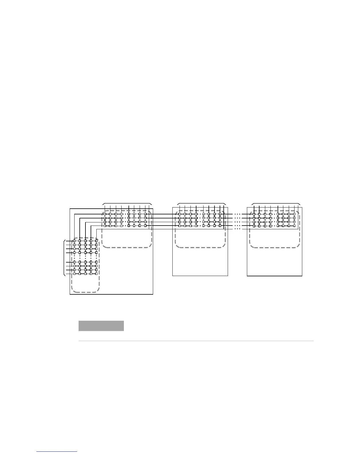
The Agilent E8782A Pin Matrix contains 40 x 4 Measurement
Matrix for switching signals to and from the Analog Bus. It also
contains a 24 x 5 Instrument Matrix that connects external
measuring instruments to the Analog Bus. The E8783A Pin
Matrix Modules contain only a 64 x 4 Measurement Matrix for
switching signals to and from the Analog Bus. Figure 6-11 is a
simplified block diagram showing how the Agilent E8782A and
E8783A are typically used together in a system. As shown in
Figure 6-11, if you need more UUT connections, simply add
more Agilent E8783A Pin Matrix Cards to the bus.
Features
Key features of the cards include:
• 24 x 5 high-speed reed relay Instrument Matrix and 40 x 4
high-speed reed relay Measurement Matrix (Agilent E8782A)
64 x 4 high-speed reed relay Measurement Matrix (Agilent
E8783A)
• An integrated relay timer
Figure 6-11 Pin Matrix Cards Conceptual Overview
40 x4
Measurem ent Matr ix
24 x 5
Instrum ent
matrix
Agilent E8782
Pin Matrix
Card
Channels
40 Measur ement
Channels
To/From UUT
64 x4
Measurement Matr ix
Agilent E8783
Pin Matrix
Card #1
64 Measur ement
Channels
To/From UUT
Analog
Bus
64 x4
Measurem ent Matr ix
Agilent E8783
Pin Matrix
Card #n
64 Measur ement
Channels
To/From UUT
Analog
Bus
The AUX channels are not shown in Figure 6-11. Refer to Figure 6-12 and
Figure 6-13 for detailed schematics of the pin matrix cards.
 Loading...


