B-2 E6198B Switch/Load Unit User Manual
B Register Definitions
Address Space
The Switch/Load Unit address space is divided as follows:
FFFSSSSSRRRRRRRR
2
where:
F = Frame select 0-7
S = Slot number 0-21 (E6918A)
R = Register offset 0-255
Use slot number 0 for Switch/Load Unit backplane access. For
Switch/Load Unit Pin Matrix, Load or Custom cards, slot
numbers are depending on the slot availability; 1-21 for E6198B.
For ease of configuration and for software auto detection, all of
the Switch/Load Unit cards (and backplane) conform to an
address map structure that begins with the three registers as
show in Table B-1.
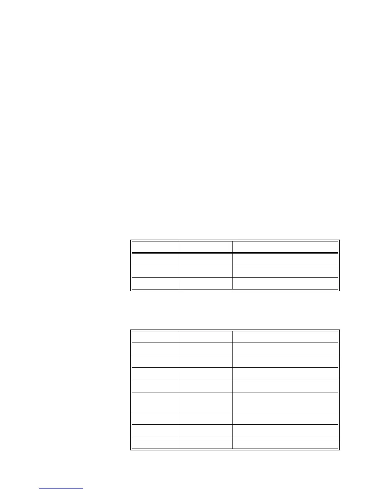
Table B-2 shows the values returned from each card’s Card
Type register.
Tabl e B-1 Standard Registers
Register Offset Register Name Description
00
h
Card type See Ta b l e B - 2 .
01
h
Card configuration Defaults to FF
h
unless changed by user.
02
h
Status/Control Card specific controls.
Tabl e B-2 Standard Registers
Model Number Card Type Value Description
Agilent E6175A 01
10
(01
h
) 8-Channel Load Card
Agilent E6176A 02
10
(02
h
)16-Channel Load Card
Agilent E6177A 03
10
(03
h
)24-Channel Load Card
Agilent U7177A 24
10
(18
h
)24-Channel Load Card
Agilent E6178B 04
10
(04
h
) 8-Channel Heavy Duty Load Card
(30 Amp)
Agilent N9378A 05
10
(05
h
) 24-Channel Low Res Load Card
Agilent N9379A 06
10
(06
h
)48-Channel Load Card
Agilent N9377A 07
10
(07
h
) 16-Dual Channel Load Card