Register Definitions B
E6198B Switch/Load Unit User Manual B-7
DAC Scaling
The DAC output voltage is determined by the following:
V
out
= (N/16,384 • 32) - 16
where N = Decimal value of DAC code programmed; MSB, LSB.
Table B-4 shows some example values of N, and the
corresponding MSBs, LSBs, and DAC voltage outputs.
Control Register (W) Base + A
h
To reset the Switch/Load Unit including DACs, Open Drain
outputs and all Load and Pin Cards, write a 1 to this register,
wait 5 mS and then write a 0 to this register. DACs will reset to
0 Vout.
To set the value of the DAC output, always write the MSB first, followed
by the LSB (register offset 9
h
). The output of the DAC will not update until
the LSB is written. See “DAC Scaling".
Bits76543210
Write
DAC1
7
DAC1
6
DAC1
5
DAC1
4
DAC1
3
DAC1
2
DAC1
1
DAC1
0
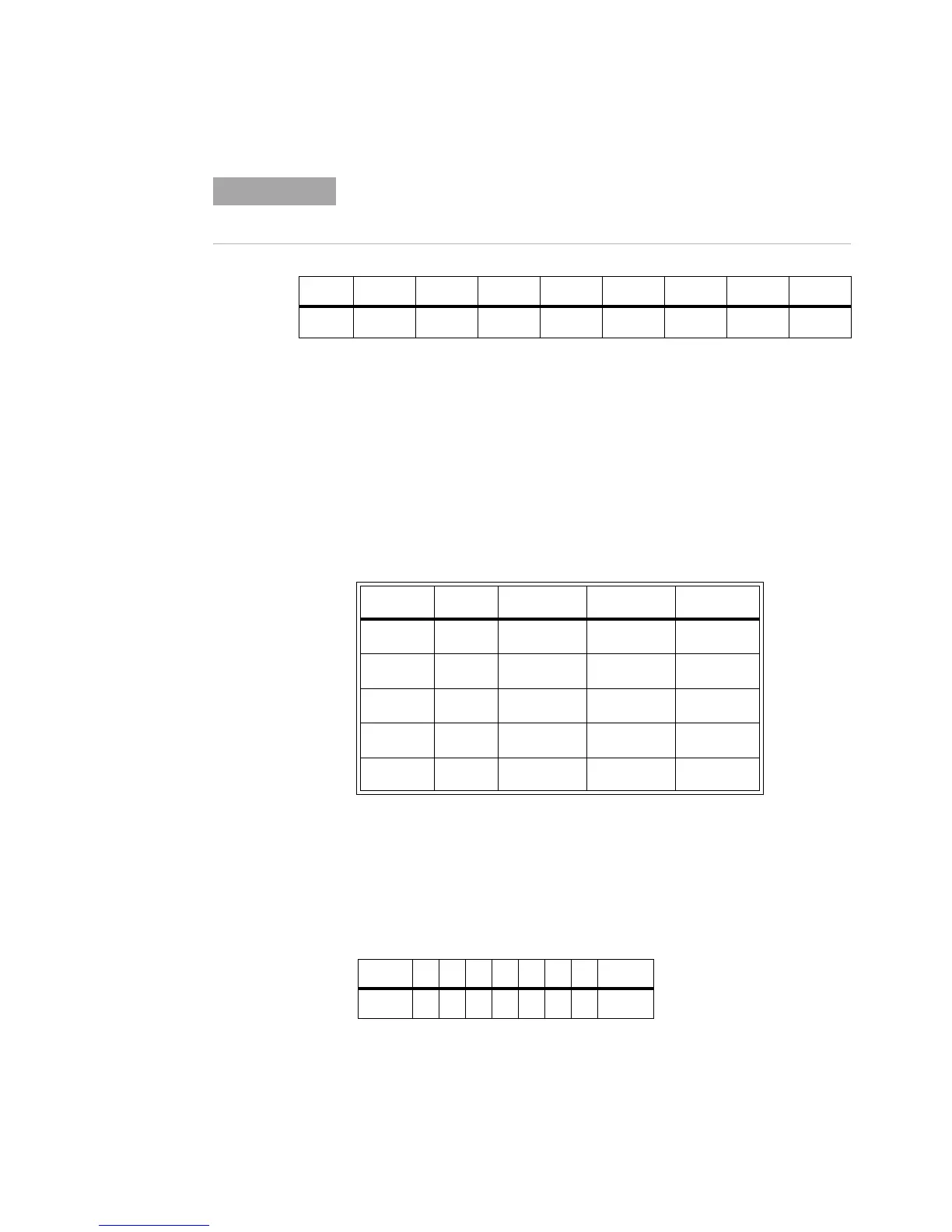
Table B-4 DAC Scaling Examples
N Hex MSB LSB DAC V
out
16383
10
3FFF
h
11111111 11111111 +16V
12288
10
3000
h
00110000 00000000 +8V
8192
10
2000
h
00100000 00000000 0V
4096
10
1000
h
00010000 00000000 -8V
0
10
0000
h
00000000 00000000 -16V
Bits 7654321 0
Write
xxxxxxxReset