5-18 E6198B Switch/Load Unit User Manual
5 Using Load Cards and Loads
shown by J6-1, J6-2, J7-3 and J7-4. Both the power source and
return are assumed to be switched through another load card to
the UUT.
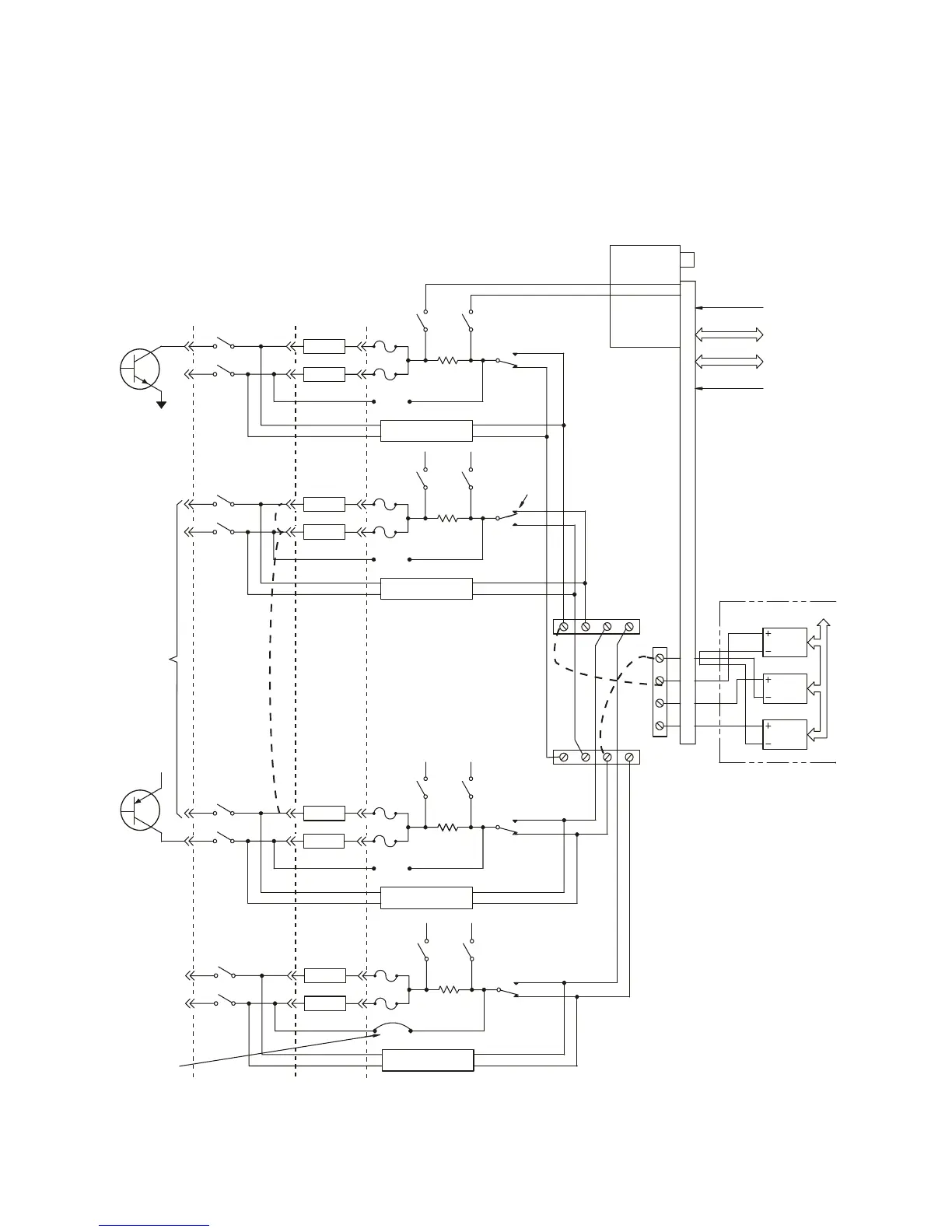
Figure 5-11 Agilent E6175A Load Examples
UUT
Loads
P2
Load
Load
Sheet
Metal
Mounted
Loads
ISense+ *2
NO
PwrSw1
NC
J6-1
R
S
Mother Board
Interface
Relay Timer
Relay Slot
Decode Logic
J2
Configuration
Connector
Current Sense
Control
Address
Data
Power
+5, ±12V
P1
J3
NO
PB1
PB2
PB3
PB4
PS #1
PS #2
PS #3
NC
J5
J4
Load
ISense- *1
ISense+ *2
NO
PwrSw3
NC
R
S
J1 odd # rows
J1 even # rows
GPIB
Load
Load
ISense- *1
NO
PwrSw2
NC
J6-2
R
S
Flyback Protection
J7-3
Load
+V
CC
Loading
Example
NPN Pull-up
Example #1
PNP Pull-down
Example #3
Bridge Load
Example #4
Multiple
Loads
Example #4
Solder-In
Jumpers
*1 are connected together
*2 are also connected together