4-10 E6198B Switch/Load Unit User Manual
4 Configuring the Switch/Load Unit
Configuring the Current-Sense Jumpers
The Switch/Load Unit is shipped from the factory with the
current-sense jumpers J2 installed in the BUSSED position
forming one continuous current-sense bus along the
Switch/Load Unit backplane. These three jumpers have been
included so that, if necessary, the existing single current-sense
bus can be split up into as many as four independent
current-sense busses by changing the jumper location to SPLIT.
Each independent current-sense bus provides one reading, so
up to four simultaneous current-sense readings can be made at
a time.
The jumpers are located into J2 connector (Figure 3-7).
Removing any jumper splits the current-sense bus at that point.
Cards to the left of the removed jumper share a current-sense
bus isolated from the one shared by the cards on the right side
of the removed jumper.
The hardware allows each card to perform current-sense
measurements on only one channel at a time. However, it is
possible to command two cards sharing a common
current-sense bus to attempt simultaneous current-sense
readings. This can lead to a power bus to power bus short,
causing confused and incorrect readings.
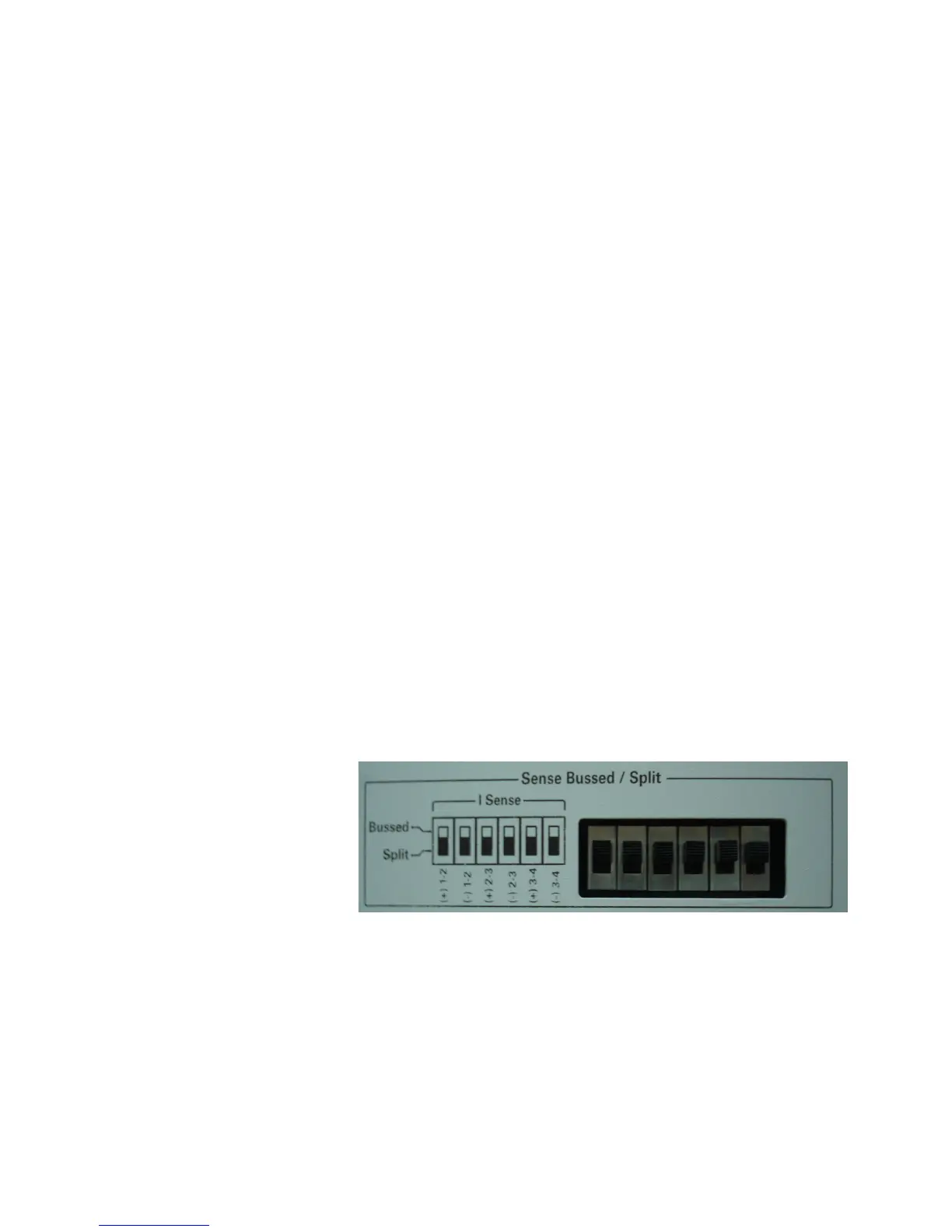
Figure 4-11 shows the ISense Bussed/Split interface for
Standalone SLU. Toggle the switch to choose either Bussed or
Split mode.
Figure 4-11 ISense Bussed/Split Interface (Standalone SLU)