Configuring the Switch/Load Unit 4
E6198B Switch/Load Unit User Manual 4-5
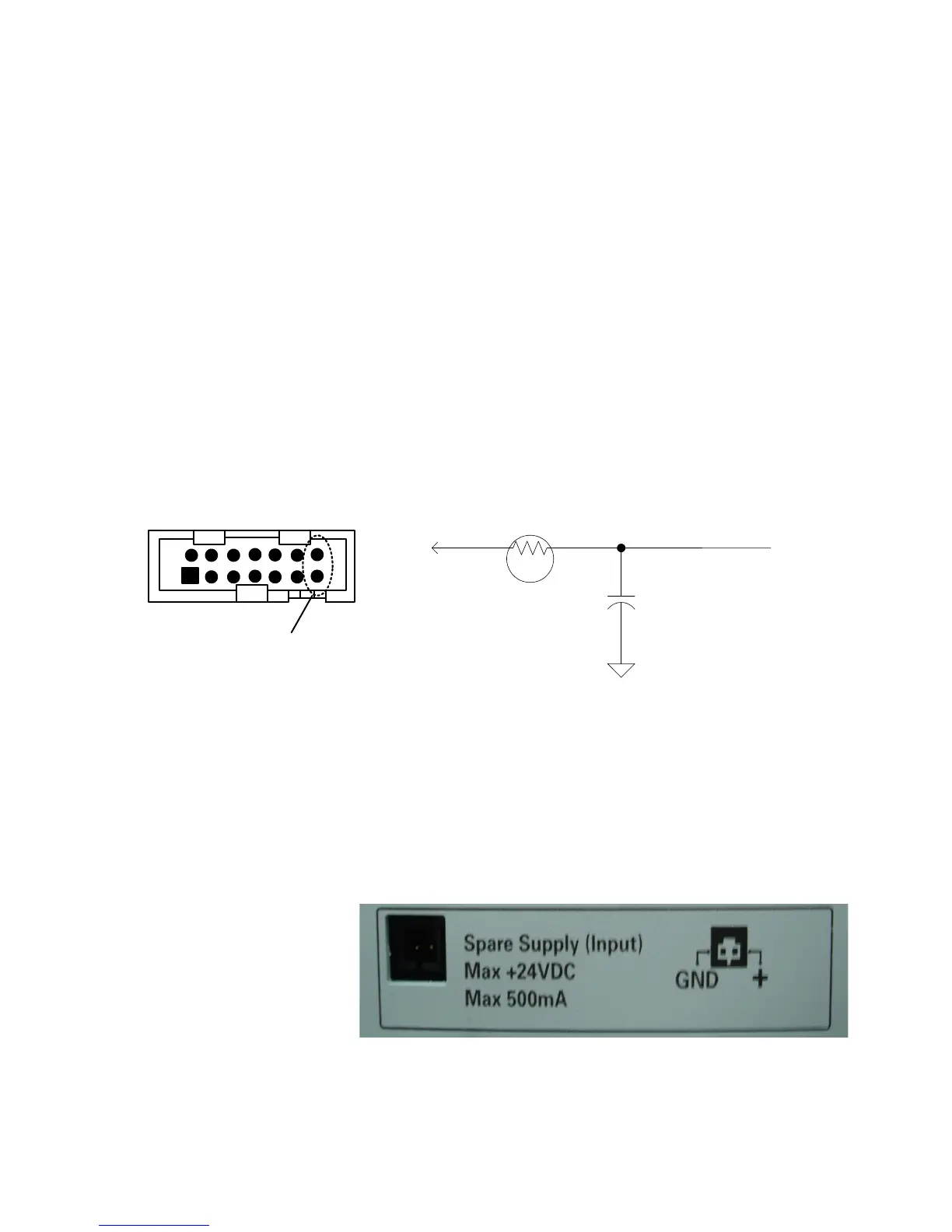
Connecting an Additional (Spare) Power Supply
Spare Supply pinout is located at Backplane connector J1 lets
you add an additional power supply such as a +24 volt power
supply for powering higher voltage relays. Figure 4-2 shows the
placement and orientation on the backplane for the power
supply components. Connector J1 is loaded at the factory.
Capacitor C507 is loaded at the factory to minimize
high-frequency noise on the supply line. The auxiliary supply
output (Spare Supply) appears on Switch/Load Unit connector
J102 pin 79 and on the Test System Interface TC2 pin N4.
For SLU Standalone option, you can connect to the Spare Supply Input
directly from SLU rear. See Figure 4-3
For SLU System Integrated Option, it is necessary to remove the SLU
rear cover to access the Spare Supply connector on the backplane.
Figure 4-2 Component Location/Schematic for User-Installed External Power Supply
C507
100uF
50V
HP 0180-3334
RT505
700m
HP 0837-0440
J1
+
Raytheon P/N
SMD100 or
equivalent
V+24V
To J102
J1
1
2
14
13
SS ( +ve Polarity)
Figure 4-3 Spare Supply (Input) Connector on SLU rear (SLU
standalone).