5-50 E6198B Switch/Load Unit User Manual
5 Using Load Cards and Loads
Connecting Loads
Loads are mounted externally and connected to the load card
via wires or cables. The loads are wired to connector P1 which
mates to the Agilent U7177A's J1 connector. Figure 5-36 shows
these connectors.
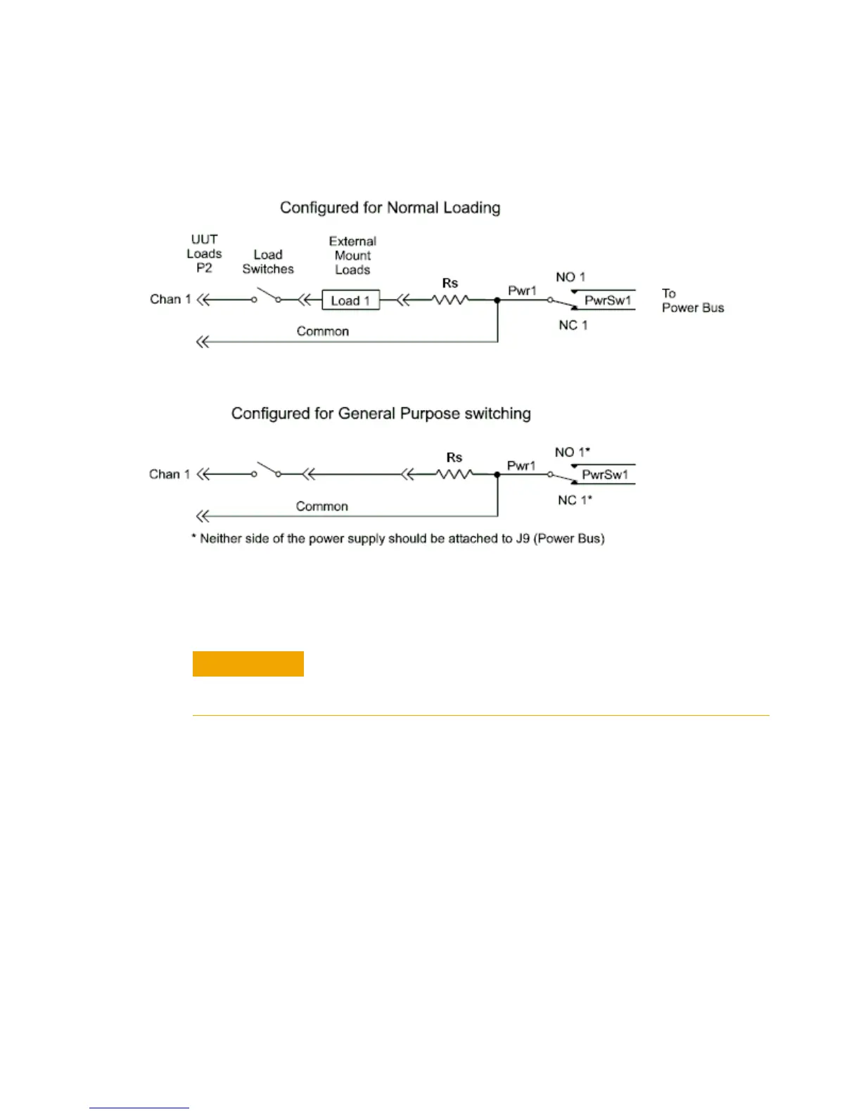
Figure 5-35 Using the 24-Channel Load Card Switches as GP Relays
When using a channel of the Agilent U7177A as a GP switch make
sure that neither the NO nor NC connectors for that channel are
jumpered to the load card power bus terminals on J9.

 Loading...


