Register Definitions B
E6198B Switch/Load Unit User Manual B-29
Status Register (R) (Base + 02
h
)
This register contains the BUSY~ bit (bit 0). The BUSY~ bit
reflects the state of all relay timers. A zero means the card is
busy setting a relay and a one means it is ready or done.
Current Sense Select (W) (Base + 03
h
)
This register controls the current sense relays of the card. Since
only one current sense channel at a time per slot is allowed,
these channel selects are encoded. This allows for a single
channel to be selected. At reset no channel is selected.
Load Select (W) (Base + 04
h
)
The register controls the Load Select switch armature relays
(K1-K8) of the card, one bit per channel. The register uses
positive logic, i.e. 1=closed. At reset no channel is selected.
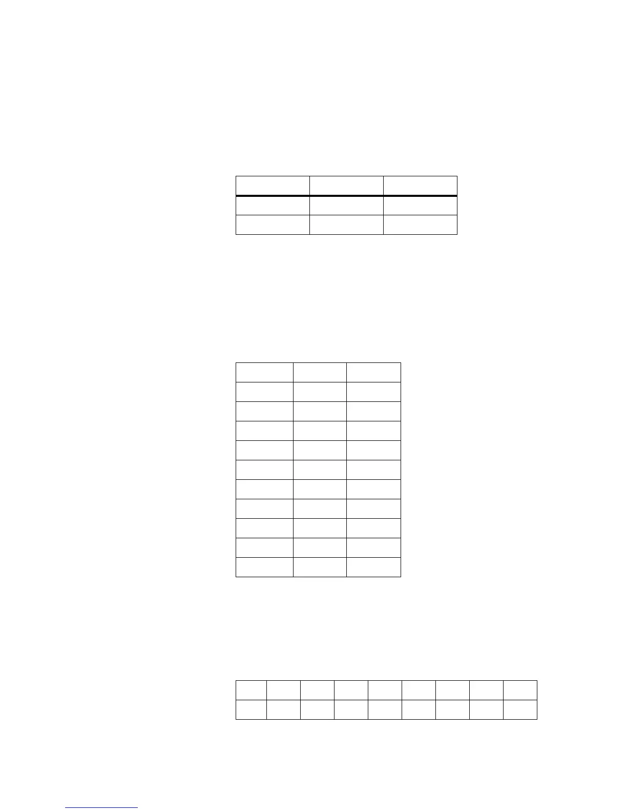
Bit 7-1 0
Purpose
Undefined BUSY~
Setting all 1s state
SELECT BITS 7-4 BITS 3-0
no channel N/A 0000
Channel 1 N/A 0001
Channel 2 N/A 0010
Channel 3 N/A 0011
Channel 4 N/A 0100
Channel 5 N/A 0101
Channel 6 N/A 0110
Channel 7 N/A 0111
Channel 8 N/A 1000
no channel N/A 1001-1111
BIT76543210
DEF
CH 8 CH 7 CH 6 CH 5 CH 4 CH 3 CH 2 CH 1