AddressS 1 A
Data1 A
SCL
Stretch
Data2
A
DataN NA P
Master to Slave
Slave to Master
RS = Repeated Start
S = Start
A = Acknowledge
P = Stop
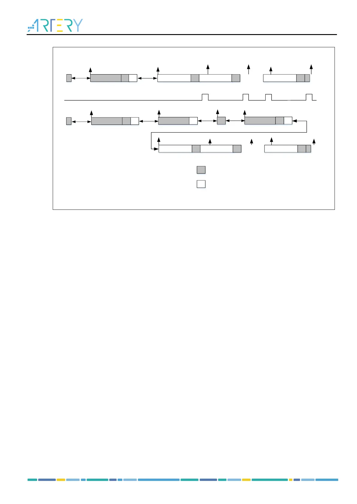
Example : I2C Master receive N bytes from I2C Slave .
EV1. I2C_STS1_STARTF=1, reading STS1 and write the address to I2C_DT will
clear the event.
EV2. I2C_STS1_ADDR7F = 1, reading STS1 and then STS2 will clear the event.
EV3. I2C_STS1_RDBF =1,reading the DT register will clear the event
EV4. I2C_STS1_RDBF =1, read the DT register and set I2C_CTRL1_ACKEN = 0
and I2C_CTRL1_GENSTOP = 1 .
EV5. I2C_STS1_ADDRHF= 1 , reading STS1 and write I2C_DT register will
clear the event .
EV2
EV3
EV4
...
RDBF
Address HeadS A
SCL
Stretch
Address A
Data1 A Data2
A
DataN NA P
EV3
EV4
...
SCL Stretch
EV3
EV3
EV3
EV3
EV2
EV5
7-bit address
10-bit address
Address HeadRS
SCL
Stretch
A
R/W
0
R/W
SCL
Stretch
EV1
SCL
Stretch
EV1
1
R/W
EV2
SCL
Stretch
EV1
7-bit address mode:
1. Generate a Start condition (GENSTART=1)
2. EV1: Start condition is ready (STARTF=1). Read STS1 and write the address to DT register.
3. EV2: Address is matched successfully (ADDR7F=1). Reading STS1 and then STS2 clears the
ADDR7F bit. In this case, the master enters receive stage.
4. EV3: The RDBF bit is set 1 after a byte is received. Reading the I2C_DT register clears the RDBF.
5. EV4: Once the second-to-last byte is received, the ACKEN bit must be cleared and the GENSTOP
must be set by software.
6. EV3: The RDBF bit is set 1 after receiving a byte. Reading the I2C_DT register clears the RDBF.
7. End of communication.
10-bit address mode:
1. Generate Start condition (GENSTART=1)
2. EV1: Start condition is ready (STARTF=1). Read STS1 and write the address to DT register.
3. EV5: 10-bit address head sequence is sent. Reading STS1 and writing to DT register can clear
the ADDRHF bit.
4. EV2: Address is matched successfully (ADDR7F=1). Reading STS1 and then STS2 clears the
ADDR7F bit, and the master re-send a Start condition (GENSTART=1).
5. EV1: Start condition is ready (STARTF=1). Read STS1 and write the address to DT register.
6. EV2: Address is matched successfully (ADDR7F=1). Reading STS1 and then STS2 clears the
ADDR7F bit. The master enters receive stage..
7. EV3: The RDBF bit is set 1 after receiving a byte. Reading the I2C_DT register clears the RDBF.
8. EV4: Once the second-to-last byte is received, the ACKEN bit must be cleared and the GENSTOP
must be set by software.
9. EV3: The RDBF bit is set 1 after receiving the byte. Reading the I2C_DT register clears the RDBF.
10. End of communication.
2. When I
2
C interrupt priority is not very high but the number of bytes to receive is greater
than 2
Do not read the third-to-last byte (N-2) that is received. Clear the ACKEN bit in the I2C_CTRL1
register after receiving the second-to-last byte (N-1). Then read the third-to-last byte (N-2), set