AT32F421 Series Reference Manual
2022.11.11 Page 258 Rev 2.02
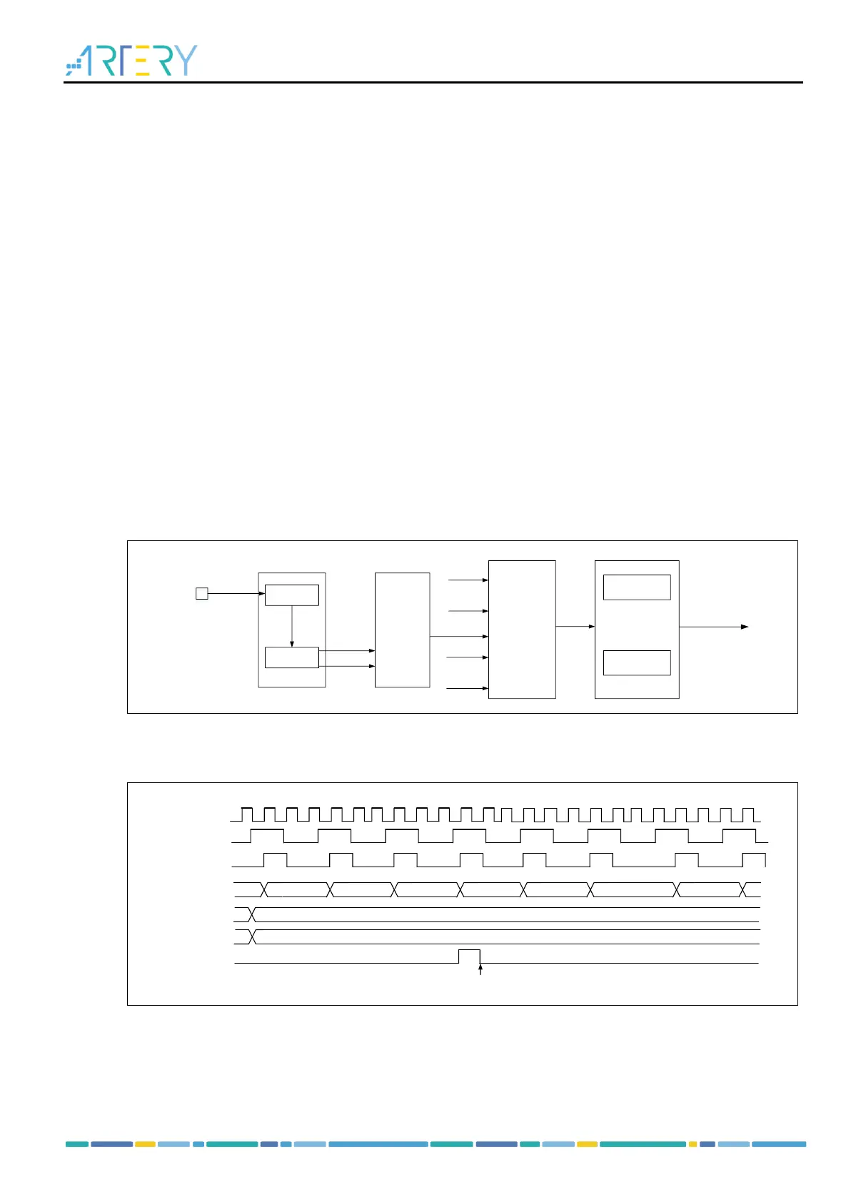
When TMRx_EXT is selected as the TRGIN, configure the external signal polarity (by setting the
ESP bit in the TMRx_STCTRL register), external signal division (by setting the ESDIV[1:0] bit in the
TMRx_STCTRL register) and external signal filter (by setting the ESF[3:0] bit in the TMRx_STCTRL
register).
– Set the TRGIN signal source by setting the STIS[1:0] bit in the TMRx_STCTRL register.
– Enable external clock mode A by setting SMSEL=3’b111 in the TMRx_STCTRL register.
– Set counter counting frequency by setting the DIV[15:0] bit in the TMRx_DIV register.
– Set counter counting period by setting the PR[15:0] bit in the TMRx_PR register.
– Enable counter by setting the TMREN bit in the TMRx_CTRL1 register.
To use external clock mode B, follow the configuration steps as below:
– Set external signal polarity by setting the ESP bit in the TMRx_STCTRL register.
– Set external signal frequency division by setting the ESDIV[1:0] bit in the TMRx_STCTRL register.
– Set external signal filter by setting the ESF[3:0] bit in the TMRx_STCTRL register.
– Enable external clock mode B by setting the ECMBEN bit in the TMRx_STCTRL register.
– Set counter counting frequency by setting the DIV[15:0] bit in the TMRx_DIV register.
– Set counter counting period by setting the PR[15:0] bit in the TMRx_PR register.
Enable counter by setting the TMREN bit in the TMRx_CTRL1 register.
Figure 14-94 Block diagram of external clock mode A