AT32F421 Series Reference Manual
2022.11.11 Page 191 Rev 2.02
Master/slave timer interconnection
Both Master and slave timer can be configured in different master and slave modes respectively. The
combination of both them can be used for various purposes. Figure 14-35 provides an example of
interconnection between master timer and slave timer.
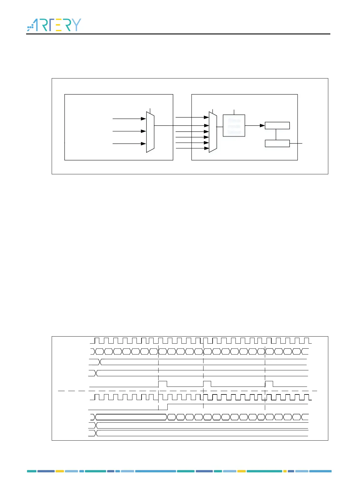
Figure 14-35 Master/slave timer connection
Using master timer to clock the slave timer:
Configure master timer output signal TRGOUT as an overflow event (PTOS[2: 0]=3’b010). The
master timer outputs a pulse signal at each counter overflow event, which is used as the
counting clock of the slave timer.
Configure the master timer counting period (TMRx_PR register)
Configure the slave timer trigger input signal TRGIN as master timer output (STIS[2: 0] in the
TMRx_STCTRL register)
Configure the slave timer to use external clock mode A (SMSEL[2: 0]=3’b111 in the
TMRx_STCTRL register )
Set TMREN =1 in both master timer and slave timer to enable them
Using master timer to start slave timer:
Configure master timer output signal TRGOUT as an overflow event (PTOS[2: 0]=3’b010). The
master timer outputs a pulse signal at each counter overflow event, which is used as the
counting clock of the slave timer.
Configure master timer counting period (TMRx_PR register)
Configure slave timer trigger input signal TRGIN as master timer input
Configure slave timer as trigger mode (SMSEL=3’b110 in the TMR2_STCTRL register)
Set TMREN=1 to enable master timer.
Figure 14-36 Using master timer to start slave timer