AT32F421 Series Reference Manual
2022.11.11 Page 190 Rev 2.02
14.2.3.5 TMR synchronization
The timers are linked together internally for timer synchronization. Master timer is selected by setting the
PTOS[2: 0] bit; Slave timer is selected by setting the SMSEL[2: 0] bit.
Slave mode includes:
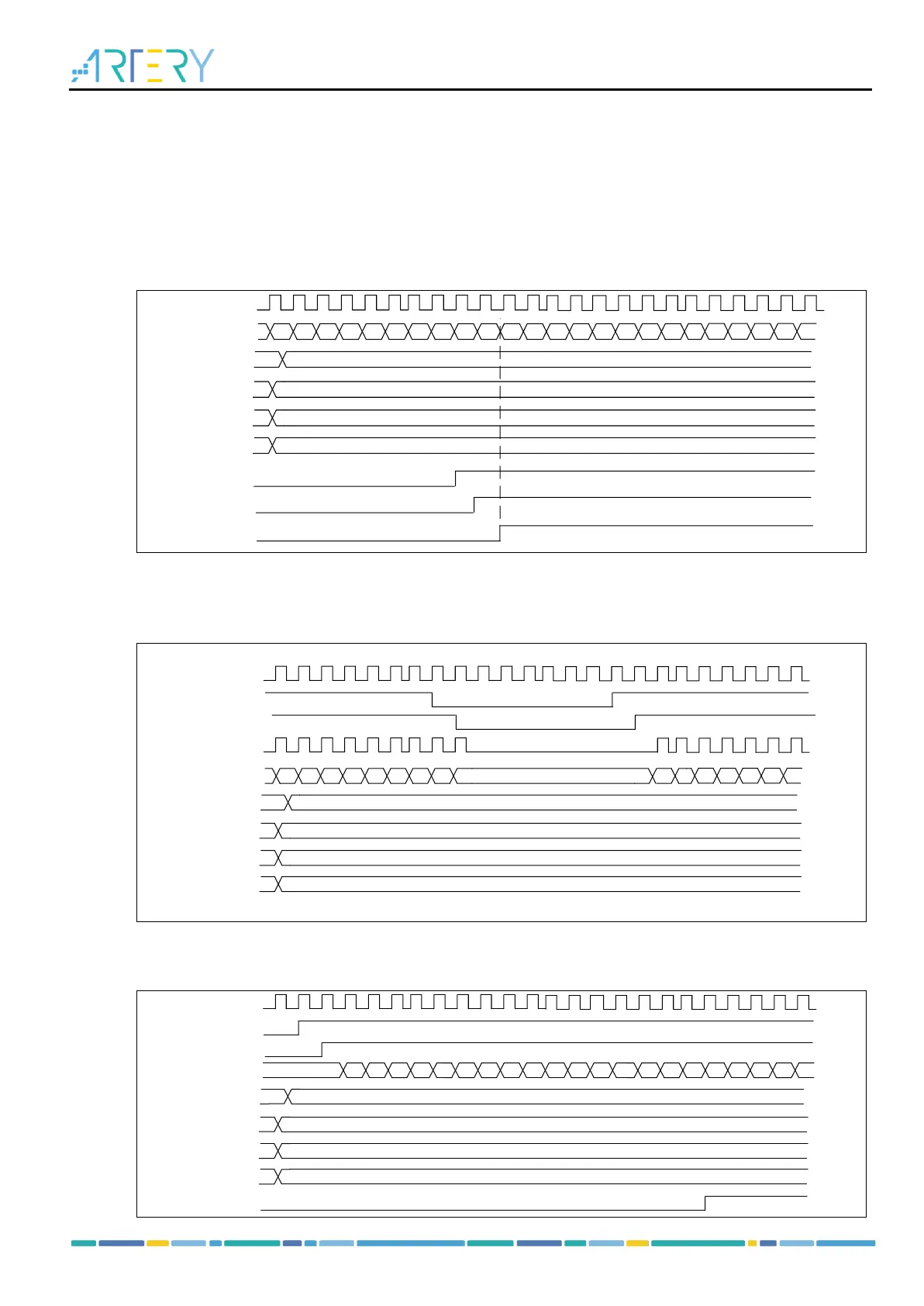
Slave mode: Reset mode
The counter and its prescaler can be reset by a selected trigger signal. An overflow event is generated
when OVFS=0.
Figure 14-32 Example of reset mode
Slave mode: Suspend mode
In this mode, the counter is controlled by a selected trigger input. The counter starts counting when the
trigger input is high and stops as soon as the trigger input is low.
Figure 14-33 Example of suspend mode
Slave mode: Trigger mode
The counter can start counting on the rising edge of a selected trigger input (TMR_EN=1)
Figure 14-34 Example of trigger mode