AT32F421 Series Reference Manual
2022.11.11 Page 205 Rev 2.02
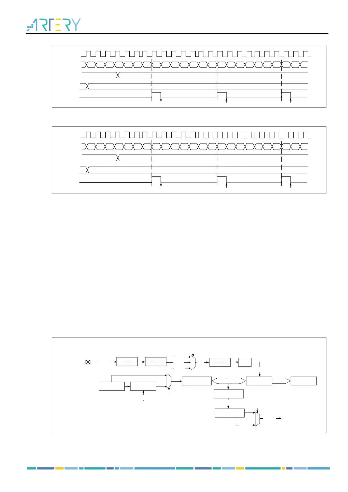
Figure 14-43 Overflow event when PRBEN=0
14.3.3.3 TMR input function
The TMR14 timer has one independent channel that can be configured as input or output. As input, each
channel input signal is processed as below:
– TMRx_CHx outputs the pre-processed CxIRAW. Set the C1INSEL bit to select TMRx_CHx as the
source of CxIRAW.
– CxIRAW inputs the digital filter and then outputs a filtered signal CxIF. Set the sampling frequency
and sampling times of digital filter by setting the CxDF bit.
– CxIF inputs the edge detector and then outputs the signal CxIFPx after edge selection. The edge
selection is controlled by CxP and CxCP bits, and can be selected as rising edge, falling edge or
both edges active.
– CxIFPx inputs the capture signal selector and then outputs the signal CxIN after selection. The
capture signal selector is controlled by the CxC bits. The source of CxIN can be set as CxIFPx. The
CyIFPx (x≠y) is the CyIFPy from channel y and handled by channel x edge detector (for example,
the C1IFP2 is the C1IFP1 from channel 1 and then handled by channel 2 edge detector).
– CxIN outputs the signal CxIPS through the input channel divider. The division factor is set to “no
division”, “divided by 2”, “divided by 4” or “divided by 8” by setting the CxIDIV bit.
Figure 14-45 Input/output channel 1 main circuit