AT32F421 Series Reference Manual
2022.11.11 Page 207 Rev 2.02
– Set CxEN bit and CxCEN bit in the TMRx_CCTRL register to enable channel output;
– Set the OEN bit in the TMRx_BRK register to enable TMRx output;
– Set the corresponding GPIO of TMR output channel as the multiplexed mode;
– Set the TMREN bit in the TMRx_CTRL1 register to enable TMRx counter.
PWM mode B: Set CxOCTRL=3’b111 to enable PWM mode B. In upcounting, when
TMRx_C1DT>TMRx_CVAL, C1ORAW outputs low; otherwise, outputs high. In downcounting,
when TMRx_C1DT<TMRx_CVAL, C1ORAW outputs high; otherwise, outputs low.
Forced output mode: Set CxOCTRL=3’b100/101 to enable forced output mode. In this case,
the CxORAW is forced to be the programmed level, irrespective of the counter value. Despite this, the
channel flag bit and DMA request still depend on the compare result.
Output compare mode: Set CxOCTRL=3’b001/010/011 to enable output compare mode. In this
case, when the counter value matches the value of the CxDT register, the CxORAW is forced high,
low or toggling.
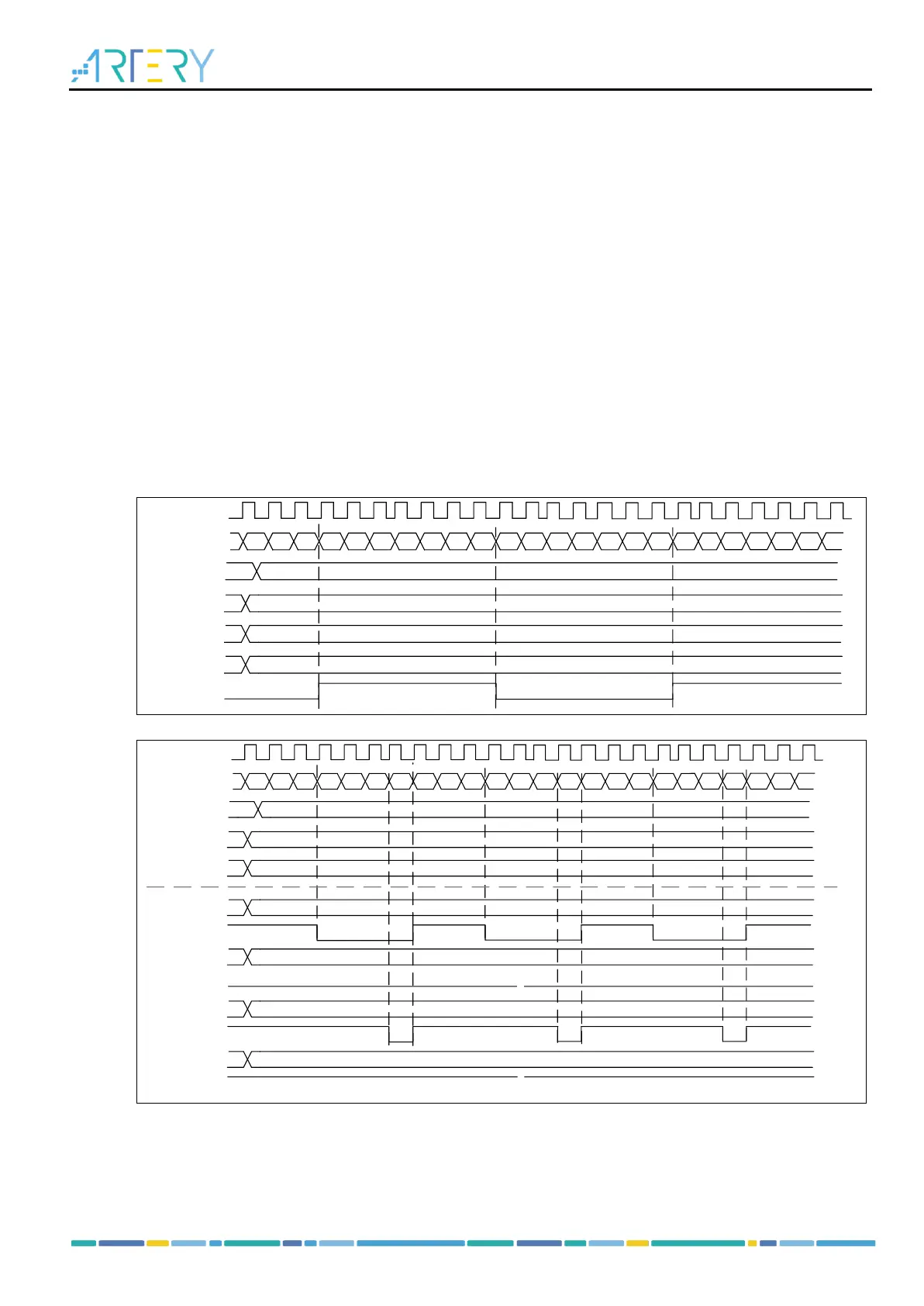
Figure 14-48 gives an example of output compare mode (toggle) with C1DT=0x3. When the counter
value is equal to 0x3, C1OUT toggles.
Figure 14-49 gives an example of the combination between upcounting mode and PWM mode A. The
output signal behaves when PR=0x32 but CxDT is configured with a different value.
Figure 14-48 C1ORAW toggles when counter value matches the C1DT value


 To Next Page