AT32F421 Series Reference Manual
2022.11.11 Page 259 Rev 2.02
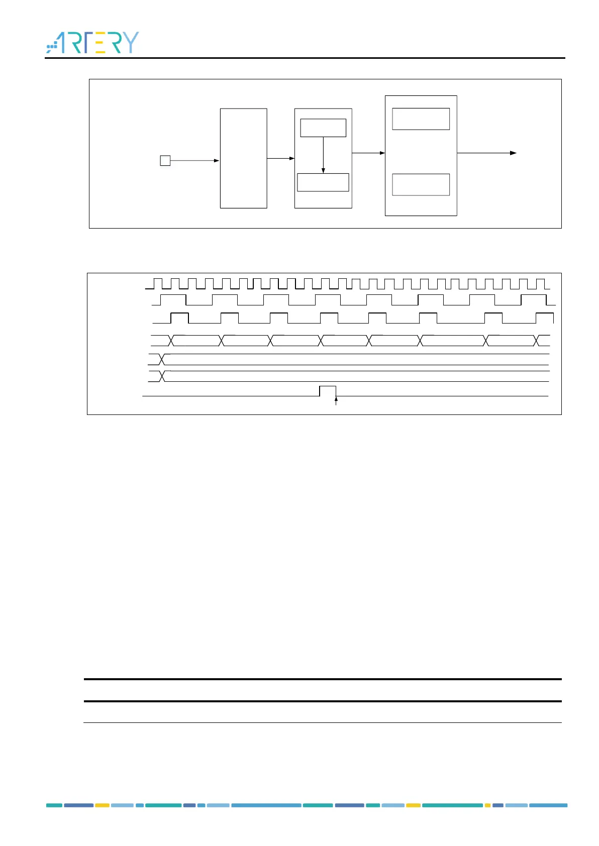
Figure 14-96 Block diagram of external clock mode B
Note: The delay is present between the signal on the input side and the actual clock of the counter due
to the synchronization circuit.
Figure 14-97 Counting in external clock mode B, with PR=0x32 and DIV=0x0
Internal trigger input (ISx)
Timer synchronization allows interconnection between several timers. The TMR_CLK of one timer can
be provided by the TRGOUT signal output by another timer. Set the STIS[2: 0] bit to select internal
trigger signal to enable counting.
Each timer consists of a 16-bit prescaler, which is used to generate the CK_CNT that enables the counter
to count. The frequency division relationship between the CK_CNT and TMR_CLK can be adjusted by
setting the value of the TMRx_DIV register. The prescaler value can be modified at any time, but it takes
effect only when the next overflow event occurs.
The internal trigger input is configured as follows:
- Set the TMRx_PR register to set counting period;
- Set the TMRx_DIV register to set counting frequency;
- Set the TWCMSEL[1:0] bit in the TMRx_CTRL1 register to set count mode;
- Set the STIS[2:0] bit (range: 3’b000~3’b011) in the TMRx_STCTRL register and select internal
trigger;
- Set SMSEL[2:0]=3’b111 in the TMRx_STCTRL register and select external clock mode A;
- Set the TMREN bit in the TMRx_CTRL1 register to enable TMRx counter.
Table 14-14 TMR1 internal trigger connection