AT32F421 Series Reference Manual
2022.11.11 Page 293 Rev 2.02
17 Enhanced real-time clock (ERTC)
17.1 ERTC introduction
The real-time clock provides a calendar clock function. The time and date can be modified by modifying
the ERTC_TIME and ERTC_DATE register.
The ERTC module is in battery powered domain, which means that it keeps running and free from the
influence of system reset and VDD power off as long as VBAT is powered.
17.2 ERTC main features
Real-time calendar (automatic processing of month days, including 28 (February in a common
year), 29 (February in a leap year), 30 (a lunar month of 30 days) and 31 (a solar month of 31
days), where the current register being a multiple of 4 indicates a leap year), a set of alarm
Reference clock detection
1 x programmable tamper detection, supporting time stamp feature
Fine and coarse calibration support
5 x battery powered registers
4 x interrupts: alarm A, periodic auto-wakeup, tamper detection and time stamp
Multiplexed function output, calibration clock output, alarm events or wakeup events
Multiplexed function input, reference clock input, one-channel tamper detection and time stamp
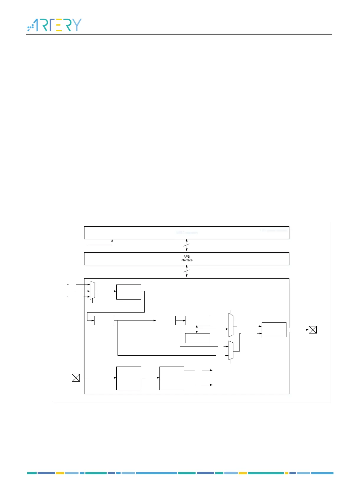
Figure 17-1 ERTC block diagram
17.3 ERTC functional overview
17.3.1 ERTC clock
ERTC clock source (ERTC_CLK) is selected via clock controller from a LEXT, LICK, and HEXT/32.
The ERTC embeds two dividers: A and B, programmed by the DIVA[6: 0] and DIVB[14: 0] respectively.
It is recommended that the DIVA is configured to a higher value in order to minimum power consumption.
After being divided by prescaler A and B, the ERTC_CLK generates ck_a and ck_b clocks, respectively.