EasyManua.ls Logo

ARTERY AT32F421C8T7 - Figure 14-66 C1 ORAW Toggles When Counter Value Matches the C1 DT Value; Figure 14-67 Upcounting Mode and PWM Mode a

Default Icon
337 pages
Print Icon
To Next Page IconTo Next Page
To Previous Page IconTo Previous Page
Loading...
AT32F421 Series Reference Manual
2022.11.11 Page 222 Rev 2.02
Figure 14-66 gives an example of output compare mode (toggle) with C1DT=0x3. When the counter
value is equal to 0x3, C1OUT toggles.
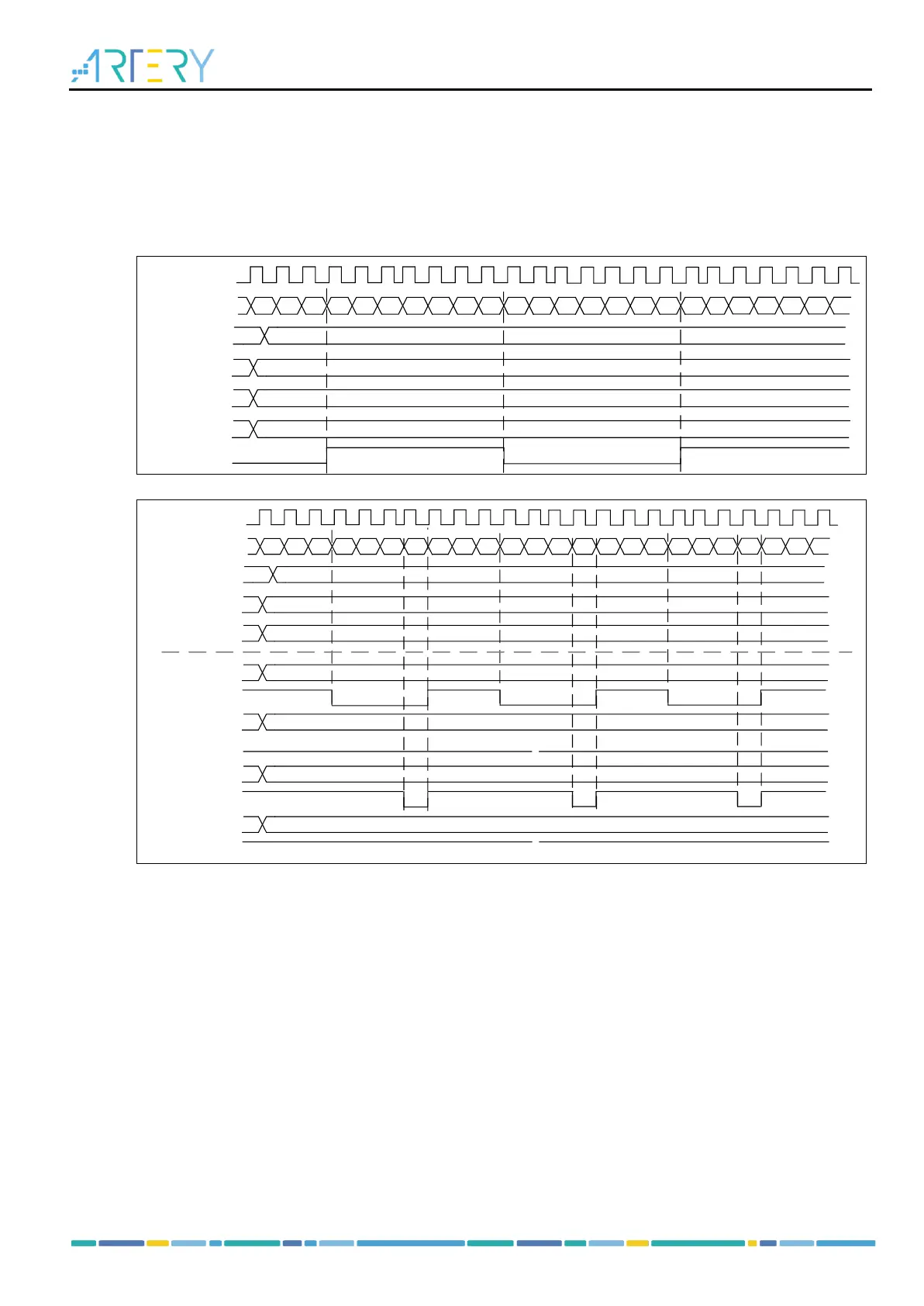
Figure 14-67 gives an example of the combination between upcounting mode and PWM mode A. The
output signal behaves when PR=0x32 but CxDT is configured with a different value.
Figure 14-68 gives an example of the combination between upcounting mode and one-pulse PWM
mode B. The counter only counts only one cycle, and the output signal sends only one pulse.
Figure 14-66 C1ORAW toggles when counter value matches the C1DT value
0 1 2 3
...
31 32 0 1 2 3
...
31 32 0 1 2 3
COUNTER
31 32 0 1
...
PR[15:0]
C1ORAW
TMR_CLK
0DIV[15:0]
32
011
C1OCTRL
[20]
3
C1DT[150]
Figure 14-67 Upcounting mode and PWM mode A
0 1 2 3
...
31 32 0 1 2 3
...
31 32 0 1 2 3
COUNTER
31 32 0 1
...
PR[15:0]
C1ORAW
TMR_CLK
0
DIV[15:0]
32
110
C1OCTRL[20]
3
C1DT[150]
C1ORAW
0
0
CIDT[150]
C1ORAW
32
C1DT[150]
1
C1ORAW
>32
C1DT[150]

Table of Contents