AT32F421 Series Reference Manual
2022.11.11 Page 262 Rev 2.02
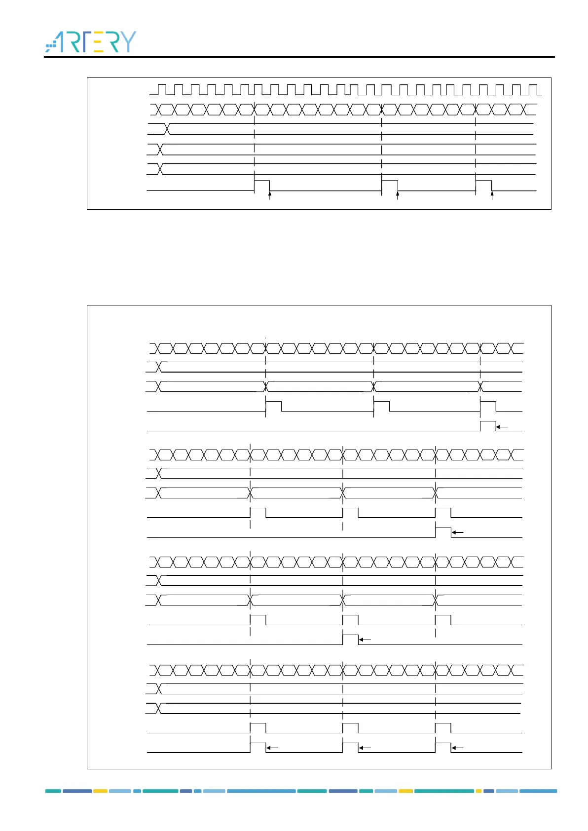
Figure 14-103 Counter timing diagram with internal clock divided by 1 and TMRx_PR=0x32
0 1 2 3
...
31 32 31 30 2F 2E
...
2 1 0 1 2 3
COUNTER
31 32 31 30
...
PR[15:0]
OVFIF
TMR_CLK
0DIV[15:0]
32
Clear Clear Clear
11
TWCMSEL
[1:0]
Repetition counter mode:
The TMRx_RPR register is used to configure the counting period of repetition counter. The repletion
counter mode is enabled when the repetition counter value is not equal to 0. In this mode, an overflow
event occurs once at every counter overflow (RPR[7:0]+1), and the repetition counter is decremented at
each counter overflow. An overflow event is generated only when the repetition counter reaches 0. The
frequency of the overflow event can be adjusted by setting the repetition counter value.
Figure 14-104 OVFIF in upcounting mode and up/down counting mode
0 1 2 3
...
31 32 0 1 2 3
...
31 32 0 1 2 3
COUNTER
31 32 0 1
2
...
RPR[7:0]
2 1 0RPR_CNT
overflow
OVFIF
2
0 1 2 3
...
31 32 31 30 2F
...
1 0 1 2 3
COUNTER
31 32 31 2F
2
...
RPR[7:0]
2 1 0RPR_CNT
overflow
OVFIF
2
30
...
1
0 1 2 3
...
31 32 31 30 2F
...
1 0 1 2 3
COUNTER
31 32 31 2F
1
...
RPR[7:0]
1 0 1RPR_CNT
overflow
OVFIF
0
30
...
1
0 1 2 3
...
31 32 31 30 2F
...
1 0 1 2 3
COUNTER
31 32 31 2F
0
...
RPR[7:0]
0RPR_CNT
overflow
OVFIF
30
...
1
clear
clear
clear
clear clear clear
Example 1 : up count mode,RPR=0x2
Example 2 : two-way up count mode3, RPR=0x2
Example 3 : two-way up count mode3, RPR=0x1
Example 4 : two-way up count mode3, RPR=0x0