AT32F421 Series Reference Manual
2022.11.11 Page 60 Rev 2.02
5 Embedded Flash memory controller (FLASH)
5.1 FLASH introduction
Flash memory is divided into three parts: main Flash memory, information block and Flash memory
registers.
Main Flash memory is up to 64 KB
Information block consists of 4 KB boot memory and the user system data area. The boot
memory uses USART1 or USART2 for ISP programming.
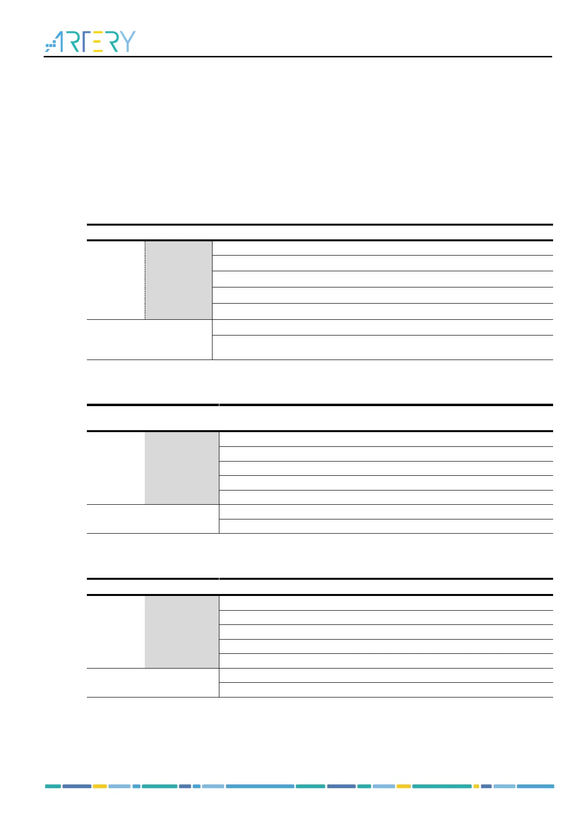
Main Flash memory contains block 1 only (64 KB), including 64 sectors, 1K per sector.
Table 5-1 Flash memory architecture(64 K)
0x0800 0000 – 0x0800 03FF
0x0800 0400 – 0x0800 07FF
0x0800 0800 – 0x0800 0BFF
0x0800 FC00 – 0x0800 FFFF
0x1FFF E400 – 0x1FFF F3FF
0x1FFF F800 – 0x1FFF F9FF
Main Flash memory contains block 1 only (32 KB), including 32 sectors, 1K per sector.
Table 5-2 Flash memory architecture(32 K)
0x0800 0000 – 0x0800 03FF
0x0800 0400 – 0x0800 07FF
0x0800 0800 – 0x0800 0BFF
0x0800 7C00 – 0x0800 7FFF
0x1FFF E400 – 0x1FFF F3FF
0x1FFF F800 – 0x1FFF F9FF
Main Flash memory contains block 1 only (16 KB), including 16 sectors, 1K per sector.
Table 5-3 Flash memory architecture(16 K)
0x0800 0000 – 0x0800 03FF
0x0800 0400 – 0x0800 07FF
0x0800 0800 – 0x0800 0BFF
0x0800 3C00 – 0x0800 3FFF
0x1FFF E400 – 0x1FFF F3FF
0x1FFF F800 – 0x1FFF F9FF