AT32F421 Series Reference Manual
2022.11.11 Page 149 Rev 2.02
13 Serial peripheral interface (SPI)
13.1 SPI introduction
The SPI interface supports either the SPI protocol or the I
2
S protocol, depending on software
configuration. This chapter gives an introduction of the main features and configuration procedure of SPI
used as SPI and I
2
S respectively.
13.2 Functional overview
13.2.1 SPI description
The SPI can be configured as host or slave based on software configuration, supporting full-duplex,
reception-only full-duplex and transmission-only/reception-only half-duplex modes, DMA transfer, and
automatic CRC function of SPI internal hardware.
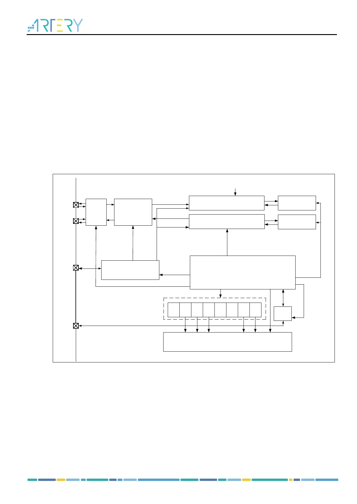
SPI block diagram:
Figure 13-1 SPI block diagram
Main features as SPI:
Full-duplex or half-duplex communication
─ Full-duplex synchronous communication (supporting reception-only mode to release IO for
transmission)
─ Half-duplex synchronous communication (transfer direction is configurable: receive or transmit)
Master or slave mode
CS signal processing mode
─ CS signal processing by hardware
─ CS signal processing by software
8-bit or 16-bit frame format
Communication frequency and prescalers (Frequency division factor up to f
PCLK
/2)
Programmable clock polarity and phase