AT32F421 Series Reference Manual
2022.11.11 Page 136 Rev 2.02
12.4 USART frame format and configuration
USART data frame consists of start bit, data bit and stop bit, with the last data bit being as a parity bit.
USART idle frame size is equal to that of the data frame under current configuration, but all bits are 1.
USART brake frame size is the current data frame size plus its stop bit. All bits before the stop bit are 0.
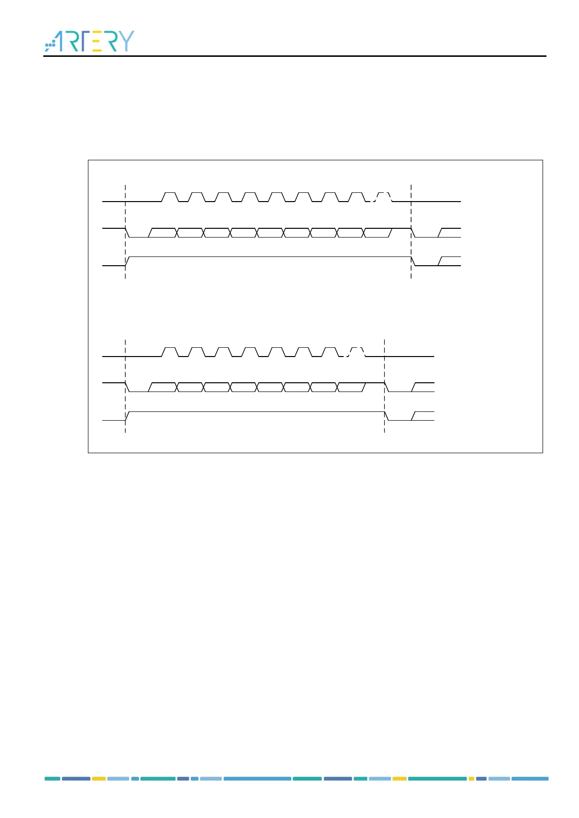
The DBN bit is used to program 8-bit (DBN=0) or 9-bit (DBN=1) data bits.
Figure 12-8 Word length
Bit 0 Bit 1 Bit 2 Bit 3 Bit 4 Bit 5 Bit 6 Bit 7 Bit 8
Start
bit
Stop
bit
9-bit word length (DBN = 1):
Next
Start
bit
Clock
Start
bit
**
Next Data frame
PEN = 1,
Parity bit
Data frame
Idle frame
Bit 0 Bit 1 Bit 2 Bit 3 Bit 4 Bit 5 Bit 6 Bit 7
Start
bit
Stop
bit
8-bit word length (DBN = 0):
Next
Start
bit
Clock
Start
bit
**
Next Data frame
PEN = 1,
Parity bit
Data frame
Idle frame
The STOPBN bit is used to program one bit (STOPBN=00), 0.5-bit (STOPBN=01), 2-bit (STOPBN=10)
and 1.5-bit (STOPBN=11) stop bits.
Set the PEN bit will enable parity control. PSEL=1 indicates Odd parity, while PSEL=0 for Even parity.
Once the parity control is enabled, the MSB of the data bit will be replaced with parity bit, that is, the
significant data bits are reduced by one bit.