AT32F421 Series Reference Manual
2022.11.11 Page 40 Rev 2.02
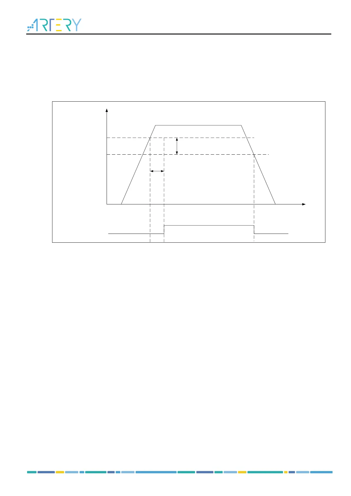
3.3 POR/LVR
A POR analog module embedded in the VDD/VDDA domain is used to generate a power reset. The
power reset signal is released at V
POR
when the VDD is increased from 0 V to the operating voltage, or
it is triggered at V
LVR
when the VDD drops from the operating voltage to 0 V. During the power-on reset
period, the reset signal release has certain amount of time delay compared to VDD boost process. At
the same time, hysteresis occurs in power-on reset (POR) and low voltage reset (LVR).
Figure 3-2 Power-on reset/Low voltage reset waveform
3.4 Power voltage monitor (PVM)
The PVM is used to monitor the power supply variations. It is enabled by setting the PVMEN bit in the
power control register (PWC_CTRL), and the threshold value for voltage monitor is selected with the
PVMSEL[2: 0] bit.
After PVM is enabled, the comparison result between VDD and the programmed threshold is indicated
by the PVMOF bit in the PWC_CTRLSTS register, with the hysteresis voltage VHYS_P being 100 mv.
The PVM interrupt will be generated (due to PVMOF level change ) through the EXTI line 16 when VDD
rises above the PVM threshold.