EasyManua.ls Logo

ARTERY AT32F421C8T7 - I;O Pin Control; USART Registers; Figure 12-13 USART Interrupt Map Diagram; Table 12-5 USART Register Map and Reset Value

Default Icon
337 pages
Print Icon
To Next Page IconTo Next Page
To Previous Page IconTo Previous Page
Loading...
AT32F421 Series Reference Manual
2022.11.11 Page 143 Rev 2.02
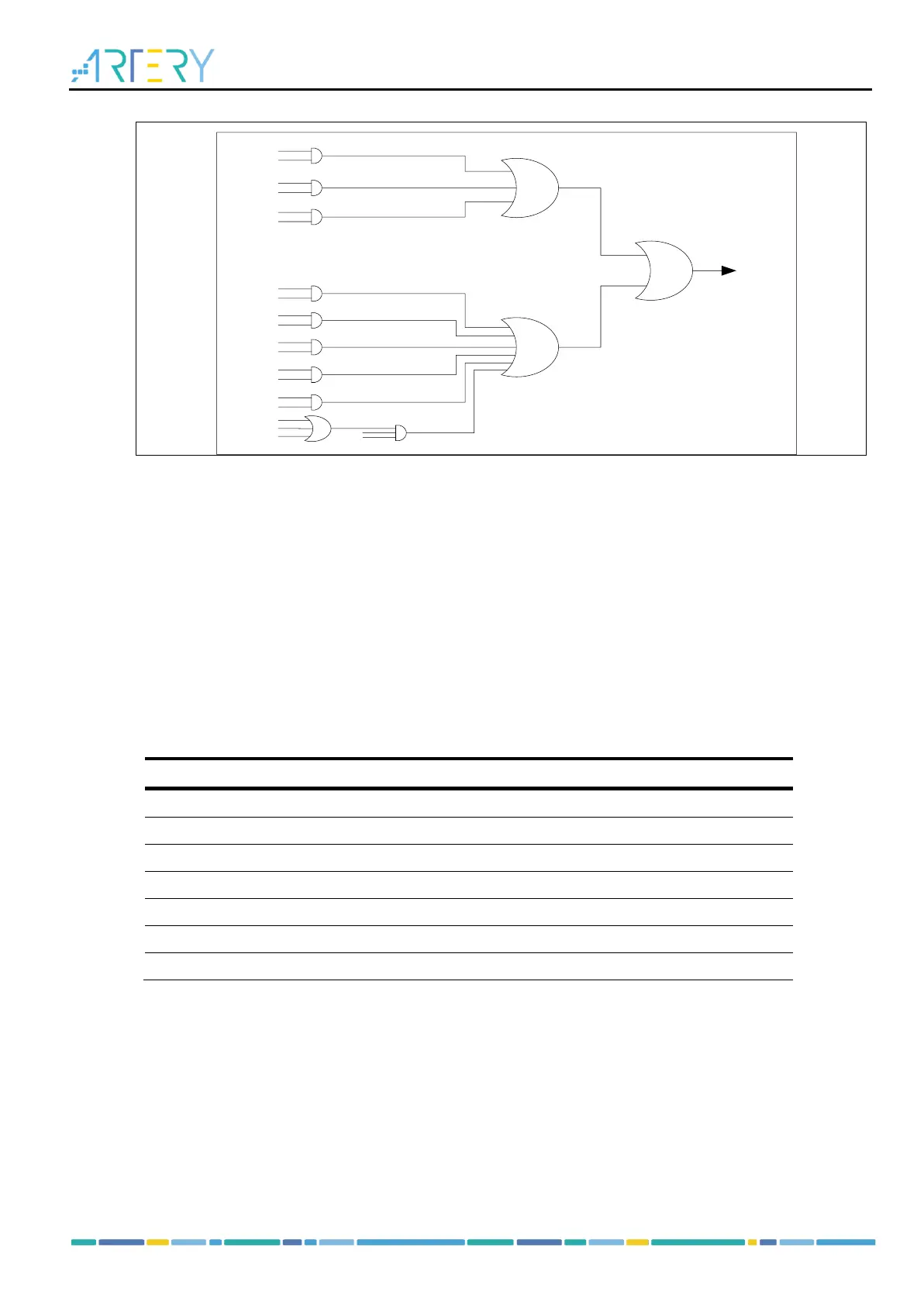
Figure 12-13 USART interrupt map diagram
USART
interrupt
TDBE
TDBEIEN
TDC
TDCIEN
CTSCF
CTSCFIEN
IDLEF
IDLEIEN
RDBFIEN
ROERR
RDBFIEN
RDBF
PERR
PERRIEN
BFF
BFIEN
FERR
NERR
ROERR
ERRIEN
DMAREN
12.11 I/O pin control
The following five interfaces are used for USART communication.
RX: Serial data input.
TX: Serial data output. In single-wire half-duplex and Smartcard mode, the TX pin is used as an I/O for
data transmission and reception.
CK: Transmitter clock output. The output CLK phase, polarity and frequency are programmable.
CTS: Transmitter input. Send enable signal in hardware flow control mode.
RTS: Receiver output. Send request signal in hardware flow control mode.
12.12 USART registers
These peripheral registers must be accessed by words (32 bits).
Table 12-5 USART register map and reset value
Register
Offset
Reset value
USART_STS
0x00
0x0000 00C0
USART_DT
0x04
0x0000 0000
USART_BAUDR
0x08
0x0000 0000
USART_CTRL1
0x0C
0x0000 0000
USART_CTRL2
0x10
0x0000 0000
USART_CTRL3
0x14
0x0000 0000
USART_GDIV
0x18
0x0000 0000

Table of Contents

Related product manuals