AT32F421 Series Reference Manual
2022.11.11 Page 82 Rev 2.02
6 General-purpose I/Os (GPIOs)
6.1 Introduction
AT32F421 series supports up to 39 bidirectional I/O pins, namely PA0-PA15, PB0-PB15, PC13-PC15,
PF0-PF1 and PF6-PF7. Each of the GPIO group supports external communication, with control and data
collection feature. In addition, their main features also include:
Supports general-purpose I/O (GPIO) or multiplexed function I/O (IOMUX)
Each pin can be configured by software as floating input, pull-up/pull-down input, analog
input/output, push-pull/open-drain output, multiplexed push-pull/open-drain output
Each pin has its respective weak pull-up/pull-down feature
Each pin’s output drive capability is configurable by software
Each pin can be configured as external interrupt input
Each pin can be locked
6.2 Functional overview
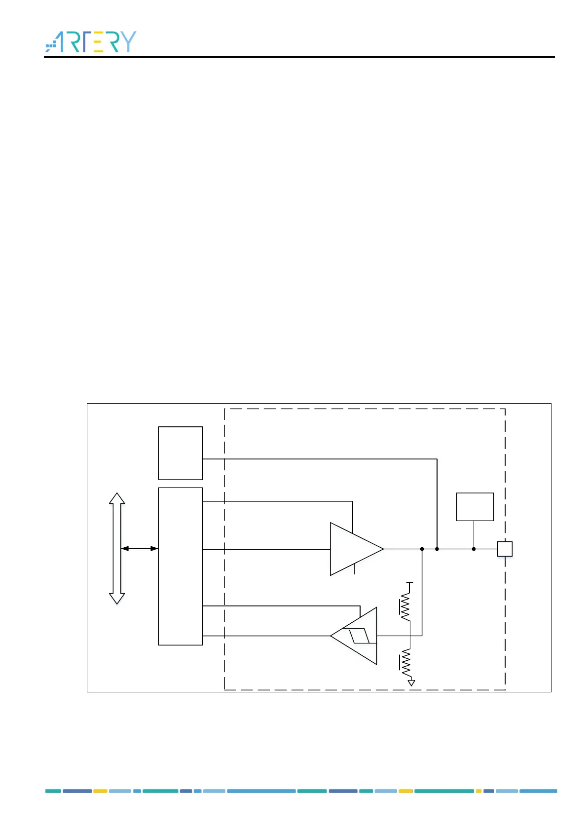
6.2.1 GPIO structure
Each of the GPIO pins can be configured by software as four input modes (floating, pull-up/pull-down
and analog input) and four output modes (open-drain, push-pull, alternate function push-pull/open-drain
output)
Each I/O port bit can be programmed freely. However, I/O port registers can be accessed by bytes, half-
bytes or words.
Figure 6-1 GPIO basic structure
6.2.2 GPIO reset status
After power-on or system reset, all pins are configured as floating input mode except SWD-related pins.
SWD-related pins are configured as follows:
PA15/SWDIO in alternate function pull-up mode;
PA14/SWCLK in alternate function pull-down mode.