AT32F421 Series Reference Manual
2022.11.11 Page 27 Rev 2.02
1.1 System overview
1.1.1 ARM Cortex
TM
-M4 processor
Cortex
®
-M4 processor is a low-power consumption processor featuring low gate count, low interrupt
latency, and low-cost debug. It supports DSP instruction set, particularly applicable to deep-embedded
applications that require quicker response to interrupts. Cortex
®
-M4 processor is based on ARMv7-M
architecture, supporting both Thumb instruction set and DSP instruction set.
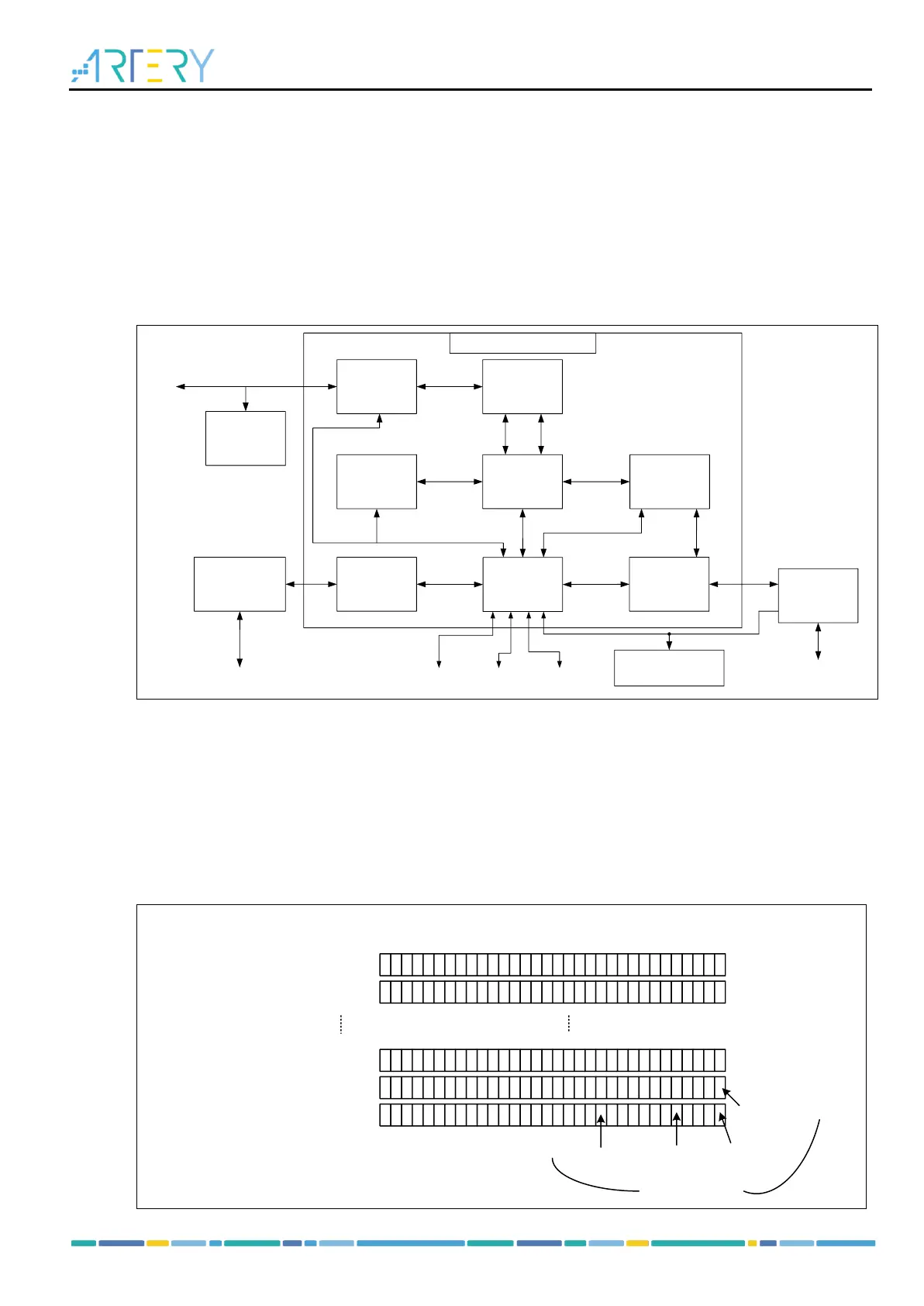
Figure 1-2 shows the internal block diagram of Cortex
®
-M4 processor. Please refer to ARM Cortex
®
-M4
Technical Reference Manual
for more information.
Figure 1-2 Internal block diagram of Cortex
®
-M4
1.1.2 Bit band
With the help of bit-band, read and write access to a single bit can be performed in the ordinary way of
loading and storing. The Cortex
®
-M4 memory includes two bit-band regions: the least significant 1M
bytes of SRAM and the least significant 1Mbytes of peripherals. In addition to access to bit-band
addresses, their respective bit-band alias region can be used to access to any bit in these two bit-band
regions. The bit-band alias region transforms each bit in it into a 32-bit word. Thus, accessing to an
address in an alias region has the same effect as read-modify-write operation on the targeted bit in a bit-
band region.
Figure 1-3 Comparison between bit-band region and its alias region: image A