AT32F421 Series Reference Manual
2022.11.11 Page 183 Rev 2.02
Figure 14-19 Counter timing diagram, internal clock divided by 1, TMRx_PR=0x32
Encoder interface mode
To enable the encoder interface mode, write SMSEL[2: 0]= 3’b001/3’b010/3’b011. In this mode, the two
inputs (C1IN/C2IN) are required. Depending on the level on one input, the counter counts up or down
on the edge of the other input. The OWCDIR bit indicates the direction of the counter, as shown in the
table below:
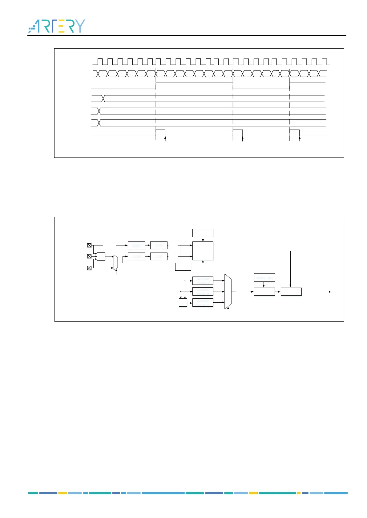
Figure 14-20 Encoder mode structure
Encoder mode A: SMSEL=3’b001. The counter counts on C1IFP1 (rising edge and falling edge), and
the counting direction is dependent on the edge direction of C1IFP1 and the level of C2IFP2.
Encoder mode B: SMSEL=3’b010, the counter counts on C2IFP2 (rising edge and falling edge), and the
counting direction is dependent on the edge direction of C2IFP2 and the level of C1IFP1.
Encoder mode C: SMSEL=3’b011, the counter counts on C1IFP1 and C2IFP2 (rising edge and falling
edge), and the counting direction is dependent on the C1IFP1 edge direction + C2IFP2 level, and
C2IFP2 edge direction + C1IFP1 level.
To use the encoder mode, follow the configuration steps as below:
– Set the C1DF[3:0] bit in the TMRx_CM1 register to set channel 1 input signal filtering; set the C1P
bit in the TMRx_CCTRL register to set channel 1 input signal active level.
– Set the C2DF[3:0] bit in the TMRx_CM1 register to set channel 2 input signal filtering; set the C2P
bit in the TMRx_CCTRL register to set channel 2 input signal active signal.
– Set the C1C[1:0] bit in the TMRx_CM1 register to set channel 1 as input mode; set the C2C[1:0] bit
in the TMRx_CM1 register to set channel 2 as input mode.
– Set the SMSEL[2:0] bit in the TMRx_STCTRL register to select encoder mode A (SMSEL=3’b001),
encoder mode B (SMSEL=3’b010) or encoder mode C (SMSEL=3’b011).
– Set the PR[15:0] bit in the TMRx_PR register to set the counting period.