AT32F421 Series Reference Manual
2022.11.11 Page 244 Rev 2.02
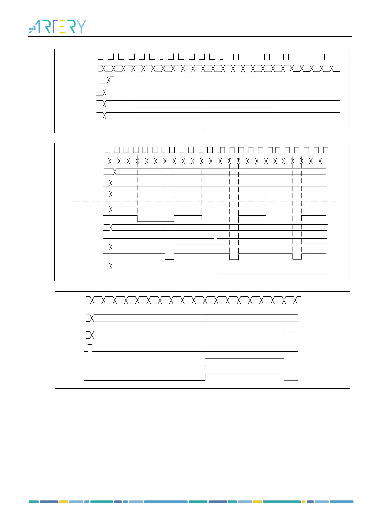
Figure 14-85 C1ORAW toggles when counter value matches the C1DT value
Dead-time insertion
The channel 1 of the TMR16 and TMR17 contains a set of reverse channel output. This function is
enabled by the CxCEN bit and its polarity is defined by CxCP. Refer to Table 14-13 for more information
about the output state of CxOUT and CxCOUT.
The dead-time is activated when switching to IDLEF state (OEN falling down to 0).
Setting both CxEN and CxCEN bits, and using DTC[7:0] bit to insert dead-time of different durations.
After the dead-time insertion, the rising edge of the CxOUT is delayed compared to the rising edge of
the reference signal; the rising edge of the CxCOU is delayed compared to the falling edge of the
reference signal.
If the delay is greater than the width of the active output, and if C1OUT and C1COUT do not generate
corresponding pulses, the dead-time should be less than the width of the active output.
Figure 14-88 gives an example of dead-time insertion when CxP=0, CxCP=0, OEN=1, CxEN=1 and