AT32F421 Series Reference Manual
2022.11.11 Page 331 Rev 2.02
21 Infrared timer (IRTMR)
The IRTMR (Infrared Timer) is used to generate the IR_OUT signal that drives the infrared LED so as to
achieve infrared control.
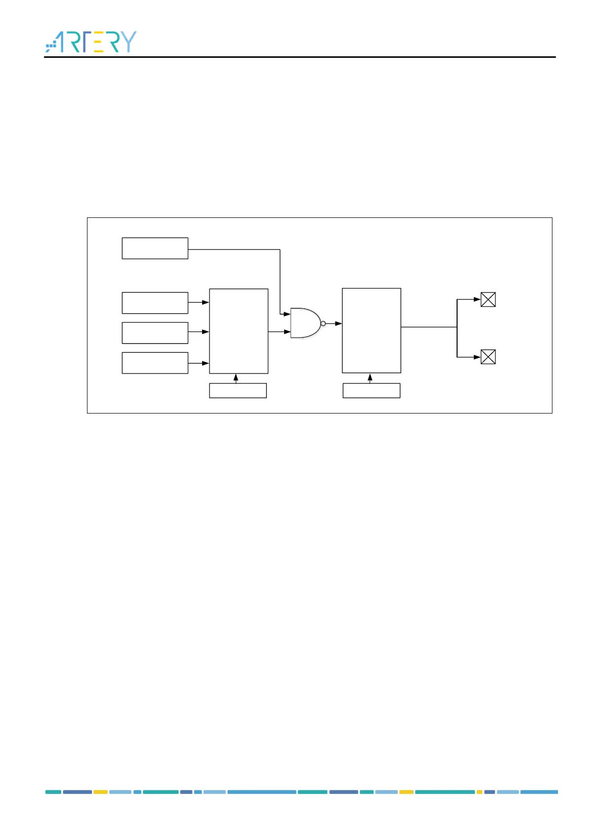
The IR_OUT signals consists of a low-frequency modulation envelope and high-frequency carrier signals.
The low-frequency modulation envelope signal selects from TMR16_C1OUT, USART1 and USART2
through the IR_SRC_SEL[1: 0] bit in the SCFG_CFG1 register, while the high-frequency carrier signal
is provided by the TMR17_C1OUT register. The IR_POL bit in the SCFG_CFG1 register controls
whether the IR_OUT output is reversed or not. The IR_OUT signal is output through multiplexed function
via PB9 or PA13 (multiplexed mode needs to be configured in advance).
Figure 21-1 IRTMR block diagram