AT32F421 Series Reference Manual
2022.11.11 Page 239 Rev 2.02
14.5 General-purpose timer (TMR16 and TMR17)
14.5.1 TMR16 and TMR17 introduction
The general-purpose timers TMR16 and TMR17 consist of a 16-bit counter supporting upcounting mode.
Each of them has a capture/compare register, and an independent channels to achieve dead-time insert,
input capture and programmable PWM output.
14.5.2 TMR16 and TMR17 main features
Source of count clock : internal clock, external clock and internal trigger
16-bit upcounter and 8-bit repetition counter
1 x independent channel for input capture, output compare, PWM generation, one-pulse mode
output and dead-time insertion
1 x independent channel for complementary output
TMR brake feature support
Synchronization control between timers
Interrupt/DMA generation on the overflow event, trigger event and channel event
Support TMR burst DMA transfer
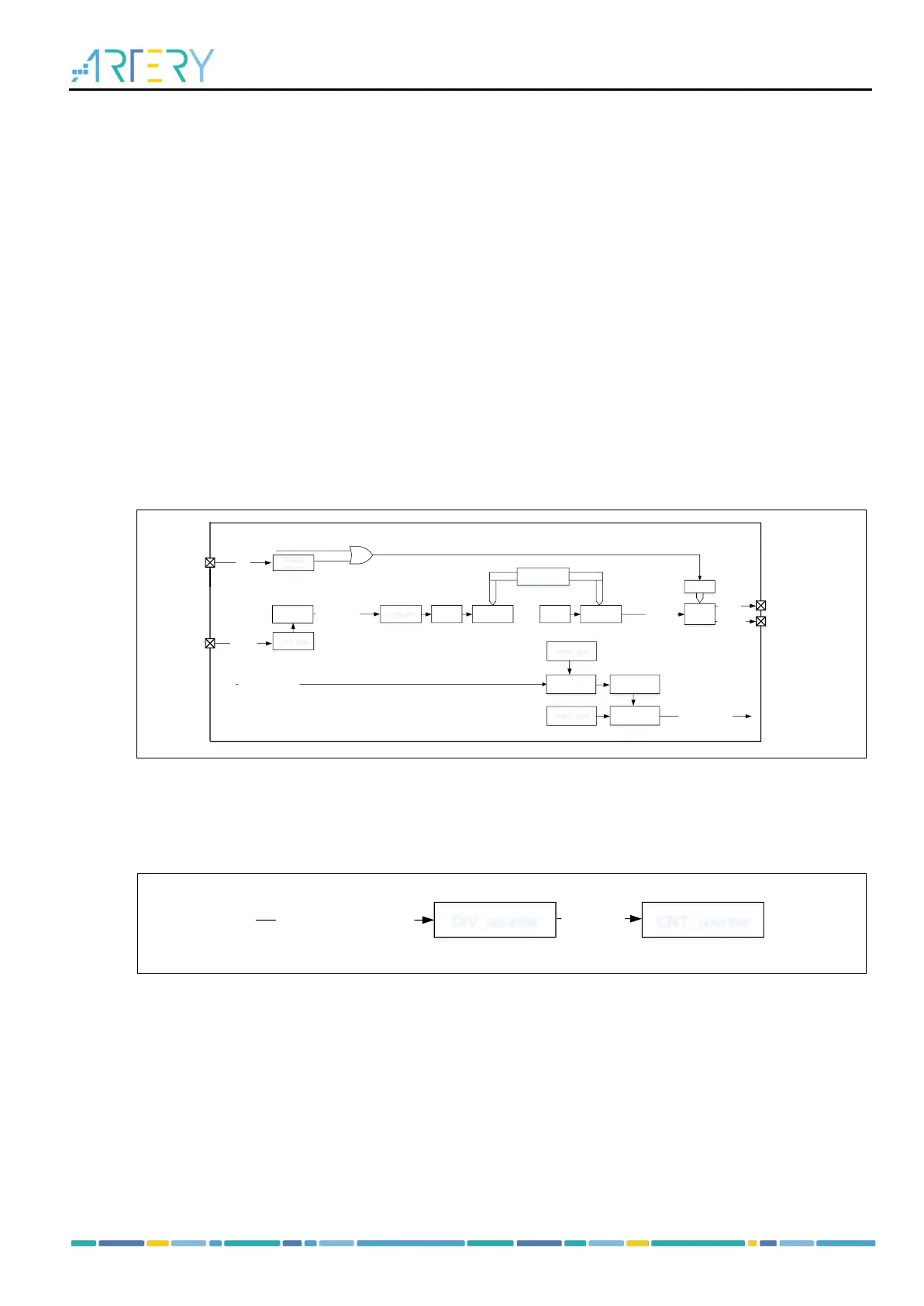
Figure 14-75 Block diagram of general-purpose TMR16 and TMR17
Internal clock (CK_INT)
By default, the CK_INT divided by a prescaler is used to drive the counter to start counting. The
configuration process is as follows:
– Set the TMRx_DIV register to set the counting frequency;
– Set the TMRx_PR register to set the counting period;
– Set the TMREN bit in the TMRx_CTRL1 register to enable the counter.