4. Installation
4.7.2.1 The input section
Overview
The input section consists of 2 input layers and a communication layer. The 2 input layers each represent one frustum:
• input layer 1:
- single link DVI input (image corresponding to one frustum)
- D15 computer input (not supported)
• input layer 2:
- single link DVI input (image corresponding to one frustum)
- D15 computer input (not supported)
• communication layer: 2x RJ45 (LAN1 and LAN2). Each LAN input is connected to one frustum image processor (PMP or Pixel
Map Processor)
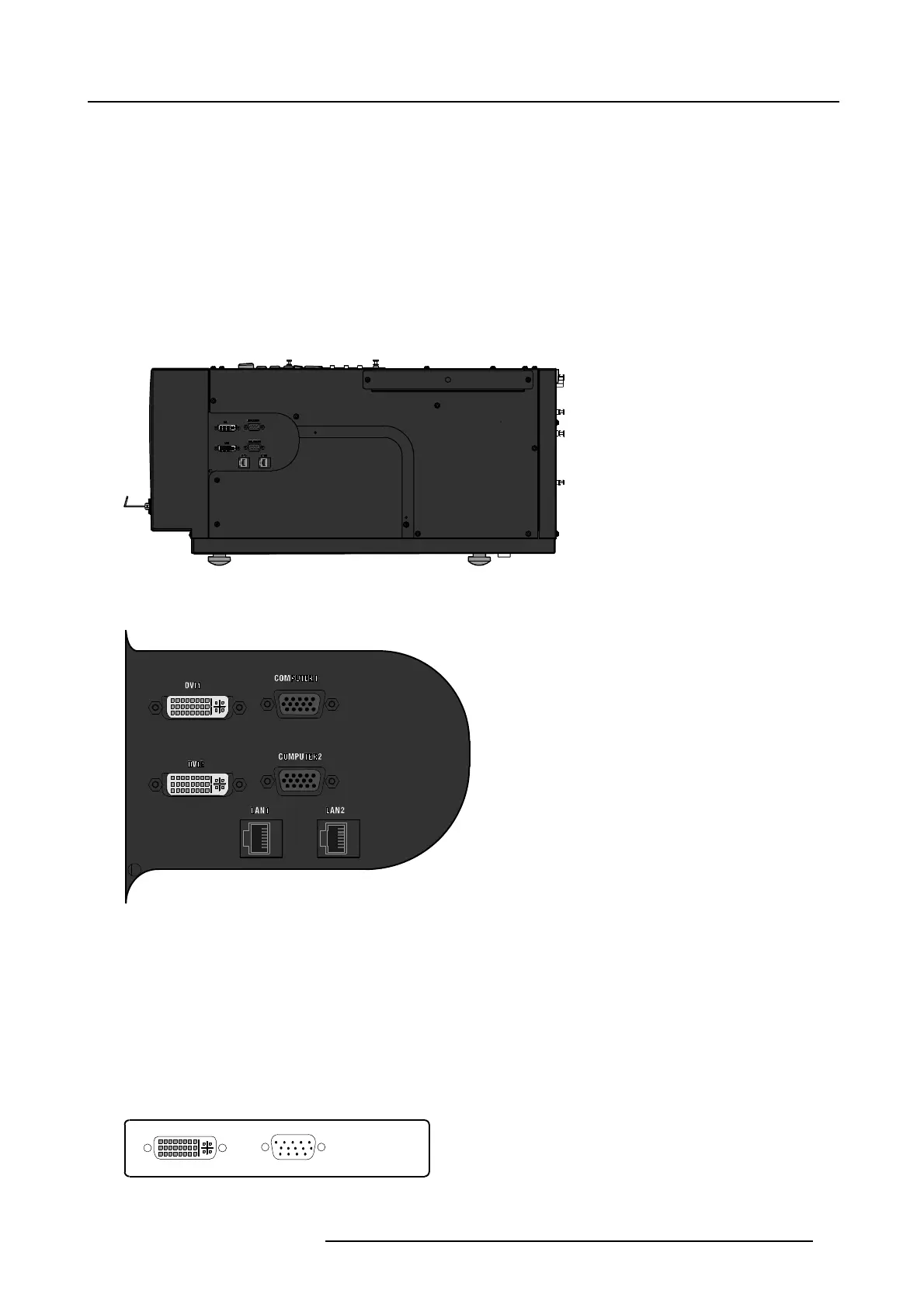
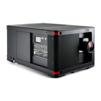
Image 4-29
Projector left side view
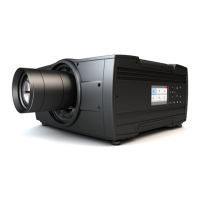
Image 4-30
Input section
4.7.2.2 Input specifications
DVI input board
This board includes :
• DVI single link digital input.
Even though the connector is of the DVI-I type, the analog part is not supported.
• D15 analog RGB input (not supported)
DVI
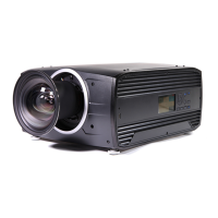
Image 4-31
DVI digital input board
R59770198 BARCO SIM 7D 13/02/2013 27