SECTION 55 - ELECTRICAL SYSTEM - CHAPTER 1
55-5
The mower-conditioner trailing light harness uses a
7-pin trailer connector to connect the mower-condi-
tioner to a tractor electrical outlet, which conforms to
SAE J560.
For proper light function, this unit must be connected
to a tractor incorporating an SAE standard 7-pin
conductor electrical socket which conforms to SAE
J560. If your tractor does not have a 7-pin conductor
electrical socket, obtain a connector socket from
your Dealer.
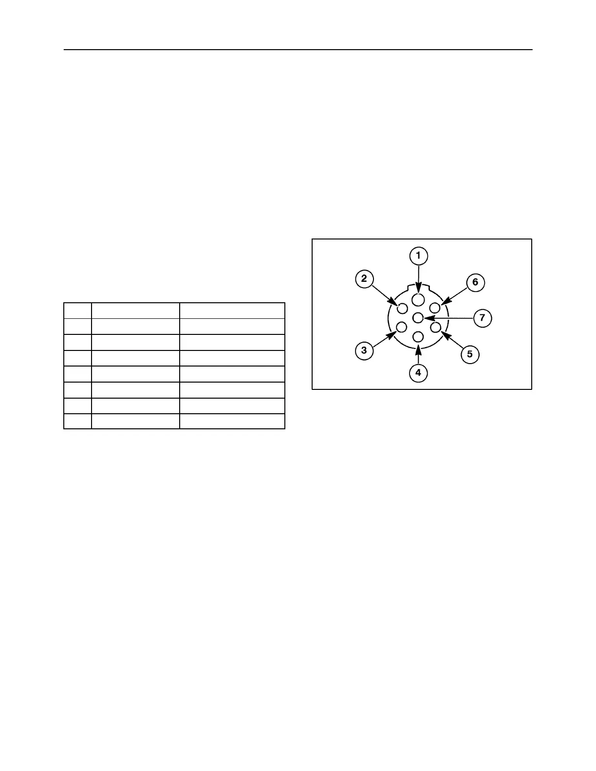
NOTE: The implement connector is shown in
Figure 7.
Installing the Socket
Use the tractor wiring diagram or, if necessary, use
a test light to identify the tractor wires. Connect the
wires to the socket as follows:
Pin
Connector ID Attached To
1 White (WHT) Ground wire, all lights
2 Black (BLK) Not used/worklights
3 Yellow (YEL) Left side amber light
4 Red (RED) Brake lights
5 Green (GRN) Right side amber light
6 Brown (BRN) Taillights
7 Blue (BLU) Not used/auxiliary
NOTE: On some tractors the wire color will not agree
with this chart.
Standard SAE J560 provides that the number 4
conductor socket of the propelling vehicle be
connected to the brake light circuit so that the brake
lights activate when the brake pedal is depressed.
Most newer model tractors are wired to provide the
brake light signal through the number 4 pin in the
connector socket. Some model tractors do not
provide this capability. On these tractors, the brake
lights on trailing implements will not function;
however, hazard, turn, and tail lamps will function.
NOTE: On some tractors, the number 4 pin in the
socket is utilized for other functions. Therefore, this
circuitry may be on all the time or any time the key
switch is on. This will cause the trailing implement
brakelightstobeonallthetime.
19985738
7