SECTION 58 - ATTACHMENTS / HEADERS - CHAPTER 3
58-20
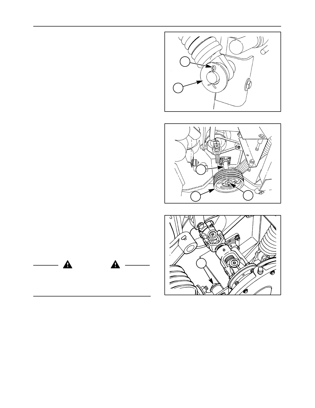
7. Reinstall the flotation spring by aligning the lower
spring mount with the brackets on the lift arm.
Insert the clevis pin, flat washer, 1, and retain
using a cotter pin, 2. Retighten the flotation
spring as required to provide correct header
flotation on the right side of the header.
19992631
1
2
51
8. Slide the drive sheave, 1, over the left end of the
conditioner roll shaft, 2, and install the thick flat
washer and 3/4″ x2″ cap screw, 3. Block the
conditioner rolls, using a block between the rolls,
or a bar through the upper roll U-joint. Tighten the
cap screw to 397 Nám (293 ft-lb) and then drive
the sheave onto the shaft using a deadblow or
soft-faced hammer. Retorque the cap screw.
Repeat this process until the cap screw no longer
loosens up when the sheave is struck.
19992640
1
2
3
52
9. The conditioner roll gearbox is easier to install if
one person holds the gearbox up to the side of
the unit while a second person installs the
retaining hardware.
Lift the conditioner roll gearbox up to the side of
the unit and rest the lower shaft flange inside the
lower roll sheave.
CAUTION
The conditioner roll gearbox is heavy and
awkward.Use caution not to drop the gearbox,as
personal injury or damage to the gearbox may
result.
Slip the cap screw, 1, through the upper gearbox
mount to support the gearbox.
A3662-1
1
53