144 • SMP Gateway User Manual
toggles between the normal and alarm – or state 0 and state 1 – colors) by selecting the Flash
checkbox.
Similarly, you can specify different colors to use when the data point’s quality is bad (ex.
communications failure).
You can also use the Font tab to edit the text’s font, style, alignment and size. Note that the
same font, style, alignment and size will be used when the data point is in alarm or when its
quality is bad.
Click OK to apply changes.
To display the real-time state of a binary input point in a cell, the configuration process is
quite similar:
Select the cell that will display a binary input’s real-time state and click the General
Properties button.
Under Select cell content, select Display binary data point.
Under Data Point, select the desired data point. You can also type the point’s name if you
prefer.
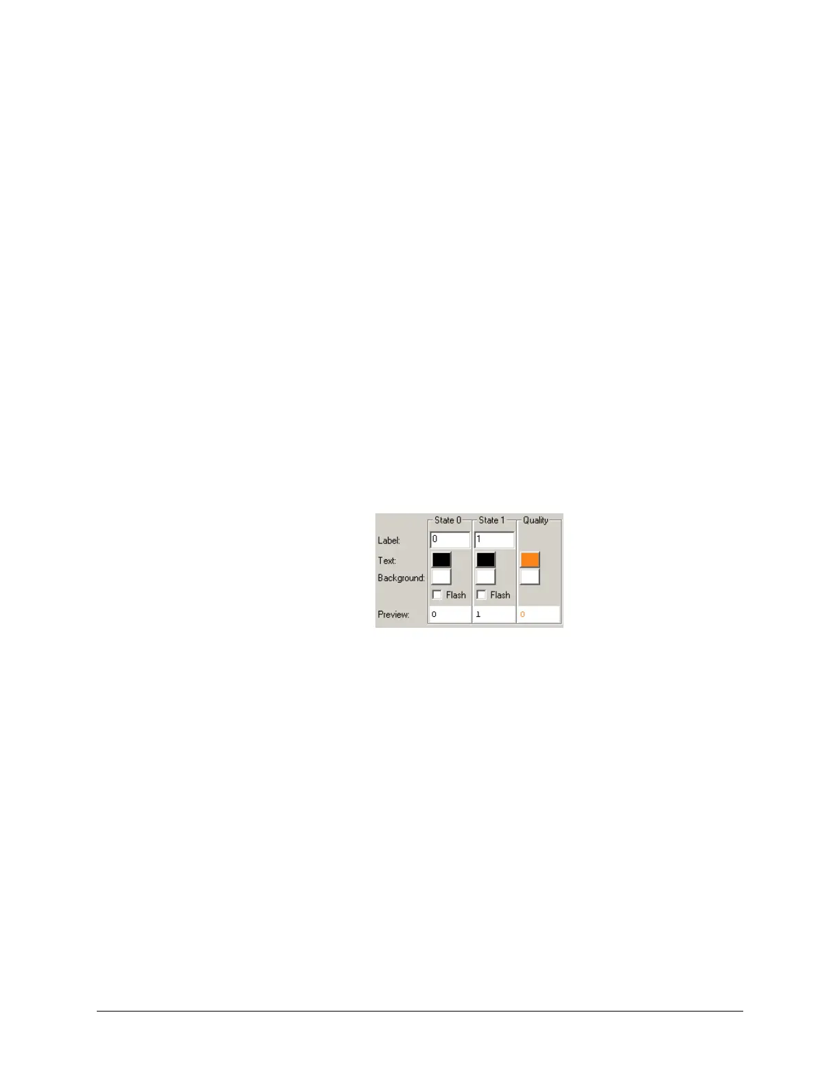
The bottom part of the General tab is a bit different than for analog data points:
Type the text to display when the input’s state is 0. For example, if the point represents the
state of a relay, you can type open. If you want the cell to blink in this state, select the Flash
checkbox.
Type the text to display when the input’s state is 1. For example, if the point represents the
state of a relay, you can type close. If you want the cell to blink in this state, select the
Flash checkbox.
You can specify the text and background colors to use while the point is in either state, or
when the point’s quality is bad.
You can also use the Font tab to edit the text’s font, style, alignment and size. Note that the
same font, style, alignment and size will be used when the data point is in alarm or when its
quality is bad.
Click OK to apply changes.