19. Malfunction code Field Service Ver. 1.0 Aug. 2005
242
bizhub 200/250/350
Troubleshooting
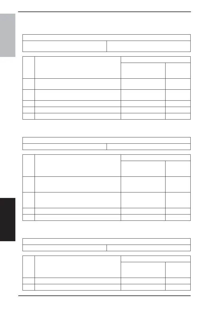
19.3.10 C2557: ATDC Sensor Failure
19.3.11 C255C: ATDC Adjustment Failure
19.3.12 C2654: EEPROM Failure
19.3.13 C2702: Abnormal Image Transfer Voltage
Relevant Electrical Parts
ATDC Sensor (UN2) Mechanical Control Board (PWB-A)
Power Supply Unit (PU1)
Step Action
WIRING DIAGRAM
Control Signal
Location
(Electrical
Component)
1
Check the UN2 connector for proper connection and
correct as necessary.
--
2
Remove the Developing Unit from the IU, and then
replace UN2.
--
3 Run F8. - -
4 Change PWB-A - -
5 Change PU1 - -
Relevant Electrical Parts
Mechanical Control Board (PWB-A)
Step Action
WIRING DIAGRAM
Control Signal
Location
(Electrical
Component)
1
Disconnect and then connect the power cord. Turn
OFF the Main Power Switch, wait for 10 sec. or
more, and turn ON the Main Power Switch.
--
2
Check the EEPROM on the Mechanical Control
Board for proper connection, and correct as neces-
sary.
--
3 Change PWB-A - -
4 Change EEPROM - -
Relevant Electrical Parts
Transfer Roller High Voltage Unit (HV1)
Step Action
WIRING DIAGRAM
Control Signal
Location
(Electrical
Component)
1 Check the installation of the Transfer Roller. - -
2 Change HV1 - -