Field Service Ver. 1.0 Aug. 2005 24. Connector layout drawing
287
bizhub 200/250/350Appendix
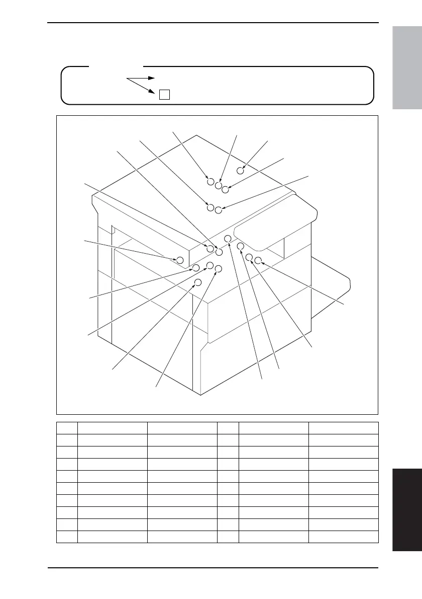
24. Connector layout drawing
No. CN No. Location No. CN No. Location
[1] CN13 L-18 to 19 [10] CN2 F-14
[2] CN25 F-15 [11] CN31 K-13
[3] CN44 L-11 [12] CN5 U-17
[4] CN81 M-12 [13] CN43 F-16
[5] CN42 L-8 [14] CN12 K-15 to 16
[6] CN45 L-9 [15] CN28 F-6
[7] CN82 L-8 [16] CN17 L-12
[8] CN4 T-17 [17] CN14 L-5 to 6
[9] CN30 L-9
Description
Number of Pin
Possible to confirm by removing external cover.
Not possible to confirm by removing external cover.
➀
1
4040F5C511DA
3
4
7
8
15
11
2
2
3
3
4
12
3
2
2
3
13
[1]
[2]
[3]
[4]
[5]
[6]
[7]
[8]
[9]
[10]
[11]
[12]
[13]
[14]
[15]
[16]
[17]