Field Service Ver. 1.0 Aug. 2005 6. Mechanical adjustment
17
PC-102/PC-202Adjustment / Setting
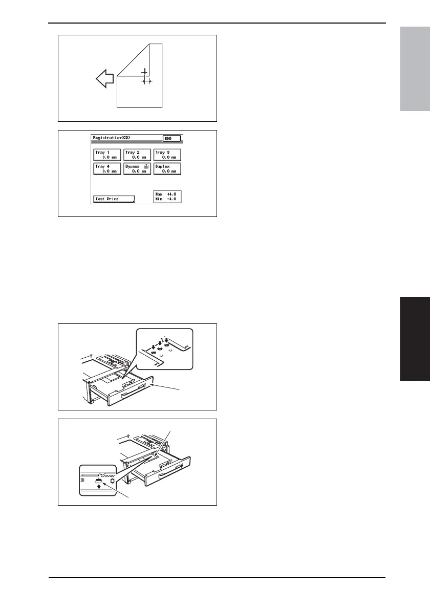
8. Measure the width of printed refer-
ence line A.
Specification: 10 mm ± 2.0 mm
9. If width A falls within the specified
range, finish the adjustment proce-
dure. If outside the specified range,
perform the adjustment below.
10. Touch [END] to display the Registra-
tion (CD) screen.
11. Touch the [Tray 3] or [Tray 4].
12. Press the Clear key and use the 10-Key Pad to set the value.
• If width A is wider than the specified range, enter a negative value.
• If width A is narrower than the specified range, enter a positive value.
Adjustment range: + 4.0 max. and -4.0 min.
Use the * key to switch between + and -.
13. Turn OFF the Main Power Switch, wait for 10 sec., then turn the switch ON.
NOTE
• If width A falls outside the specified range, redo the adjustment from step 13.
14. Slide out the Tray [1] and unload
paper from it.
15. Loosen three screws [2] at the center
of the Paper Lifting Plate.
16. Watching the graduations [3] pro-
vided in the drawer, move the Edge
Guide [4] in the rear.
• If width A is greater than the specified
value, move the Edge Guide toward
the front.
• If width A is smaller than the specified
value, move the Edge Guide toward
the rear.
17. Perform another test print and check the reference deviation.
18. Repeat the adjustment until the reference line falls within the specified range.
19. Tighten the adjustment screw.
20. Repeat steps 1 to 19 similarly for the tray 4.
4061F3C505DA
A
4061F3C519DA
4348fs3601c0
[1]
[2]
4348fs3602c0
[4]
[3]