6.2.1 Channel Mapping Tab
6.2.1.1 Disabled Configuration
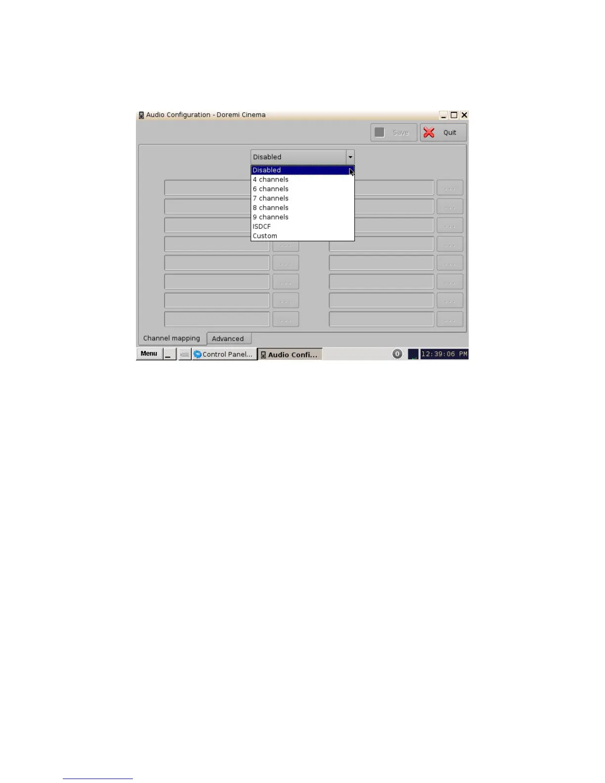
Figure 24: Disabled Configuration
• Disabled: This setting is the default and as such cannot be mapped. The Disabled mapping
configuration will perform pass-through mapping, meaning channel number "X" of the CPL
audio track will be routed to audio output number "X" (variable) of the server. "X" being a
number between 1 and 16. When the configuration is grayed-out, the user cannot change
the configuration.
6.2.1.2 Pre-Defined Mapping Configurations
6.2.1.2.1 4 Channels
This configuration is defined as follows (Figure 25):
• ch.01 is Left (L): Output ch.01 will be playing the CPL's Left (L) audio channel.
• ch.02 is Right (R): Output ch.02 will be playing the CPL's Right (R) audio channel.
• ch.03 is Center (C): Output ch.03 will be playing the CPL's Center (C) audio channel.
• ch.04 is Input: ch.04 is pass-through, meaning the output channel “X” will be playing the
CPL's audio channel “X.”
• ch.05 is Surround (S): Output ch.05 will be playing the CPL's Surround (S) audio channel.
• Channels ch.06 - ch.14 are pass-through, meaning the output channel “X” will be playing
the CPL's audio channel “X.” “X” will be a value between 6 and 14.
• ch.15 is HI: Output ch.15 will be playing the CPL's Hearing Impaired (HI) audio channel.
• ch.16 is VI: Output ch.16 will be playing the CPL's Narration (VI) audio channel.
______________________________________________________________________________________
D2K.OM.001822.DRM Page 24 of 177 Version 1.5
Doremi Labs