Short thread cutter (KFA)
Service Instructions M-TYPE DELTA - 00.0 - 12/2019 87
5. Turn the control cam (5) such that area A is next to the roller (3).
6. Screw in the threaded pin (7) until the distance between roller (3) and
control cam (6) is 0.1 ± 0.05 mm.
The threaded pin (3) makes contact with the set collar (4).
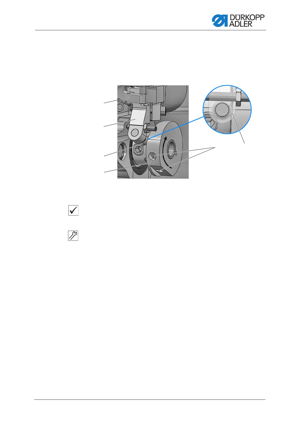
Fig. 71: Adjusting the control cam sideways (2)
Proper setting
When the machine is locked in place in the looping stoke position,
the roller (3) is positioned exactly in the adjustment slot (10).
7. Lock the machine in place ( p. 32).
8. Loosen the threaded pins (9).
9. Release the latch (8).
10. Swing out the lever (2).
11. Turn the control cam (5) in the direction of the arrow until the roller (3) is
positioned exactly in the adjustment slot (10).
12. Push the control cam (5) as far as it will go to the left.
13. Tighten the threaded pins (9).
(2) - Lever
(3) - Roller
(5) - Control cam
(8) - Latch
(9) - Threaded pins
(10) - Adjustment slot
 Loading...