User Manual Section 4
GFK-2958L May 2021
Detailed Descriptions of the Fieldbus Network Adapters 95
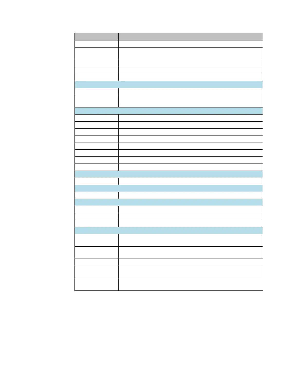
Analog Input, 8 Channels Current 16 Bits 2-, 3-, or 4-Wire
Analog Input, 8 Channels Current 16 Bits 2-, 3-, or 4-Wire, Channel
Diagnostic
Analog Input, 4 Channels RTD 16 Bits with Diagnostics 2-, 3-, or 4-Wire
Analog Input, 4 Channels TC 16 Bits with Diagnostics 2-, 3-, or 4-Wire
Power Measurement Module, 8 Channels
Analog Output, 4 Channels Voltage/Current 16 Bits 2-, 3-, or 4-Wire
Analog Output, 4 Channels Voltage/Current 16 Bits with Diagnostics 2-, 3-
, or 4-Wire
1 Channel High Speed Counter, AB 100 kHz 1 DO 24Vdc, 0.5A
2 Channel High Speed Counter, AB 100 kHz
2 Channel Frequency Measurement, 100 kHz
1 Channel Serial Communications, 232, 422, 485
1 Channel SSI Encoder, BCD or Gray-Code Format, 5/24 Vdc
2 Channels PWM Output, Positive Logic, 24Vdc, 0.5 A
2 Channels PWM Output, Positive Logic, 24Vdc, 2 A
IO-Link Communication module, 4 Channels
Power Feed Modules for Input Current Path
Power Module, 1 Channel 24Vdc Input Flow 10A
Power Feed Modules for Output Current Path
Power Module, 1 Channel 24Vdc Output Flow 10A
1 Safe Feed-Input, 24 Vdc
2 Safe Feed-Inputs, 24 Vdc, Programmable Delay
2 Safe Feed-Inputs, 24 Vdc
Potential Distribution Modules
Power Module, 16 Channels 24Vdc Potential Distribution +24Vdc from
Input Current Path
Power Module, 16 Channels 24Vdc Potential Distribution +24Vdc from
Output Current Path
Power Module, 16 Channels 24Vdc Potential Distribution Functional Earth
Power Module, 16 Channels 24Vdc Potential Distribution +0Vdc from Input
Current Path
Power Module, 16 Channels 24Vdc Potential Distribution +0Vdc from
Output Current Path

 Loading...


