User Manual Section 5
GFK-2958L May 2021
Detailed Description of I/O Modules 274
In another output word the output mode is switched, and the output is being started and
stopped. Deactivated outputs are set to GND.
For each channel the current status can be read in a status word. A status LED is assigned to
each channel. The outputs are supplied with power from the output current path (IOUT).
The module is protected against external voltages between 0 V and the operating voltage.
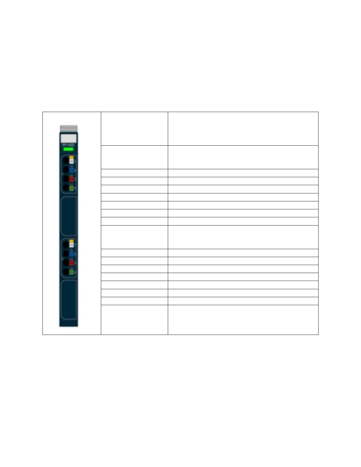
5.21.1 LED Indicators EP-5422
Green: Communication over the system bus
Red: Module System Fault or Diagnostic Fault
Yellow: PWM output 0 – 100%, P-switching
Yellow flashing at 2 Hz: PWM output 0 is > 0 and < 100%,
PN-switching or P-switching
Yellow: PWM output 1 – 100%, P-switching
Yellow flashing at 2 Hz: PWM output 0 is > 0 and < 100%,
PN-switching or P-switching
For error messages refer to Section 12, LED Indicators and Troubleshooting.

 Loading...


