User Manual Section 7
GFK-2958L May 2021
Earthing and shielding 421
—
DC load circuits that cannot be coupled
Potential-free installation depends on the type of earthing.
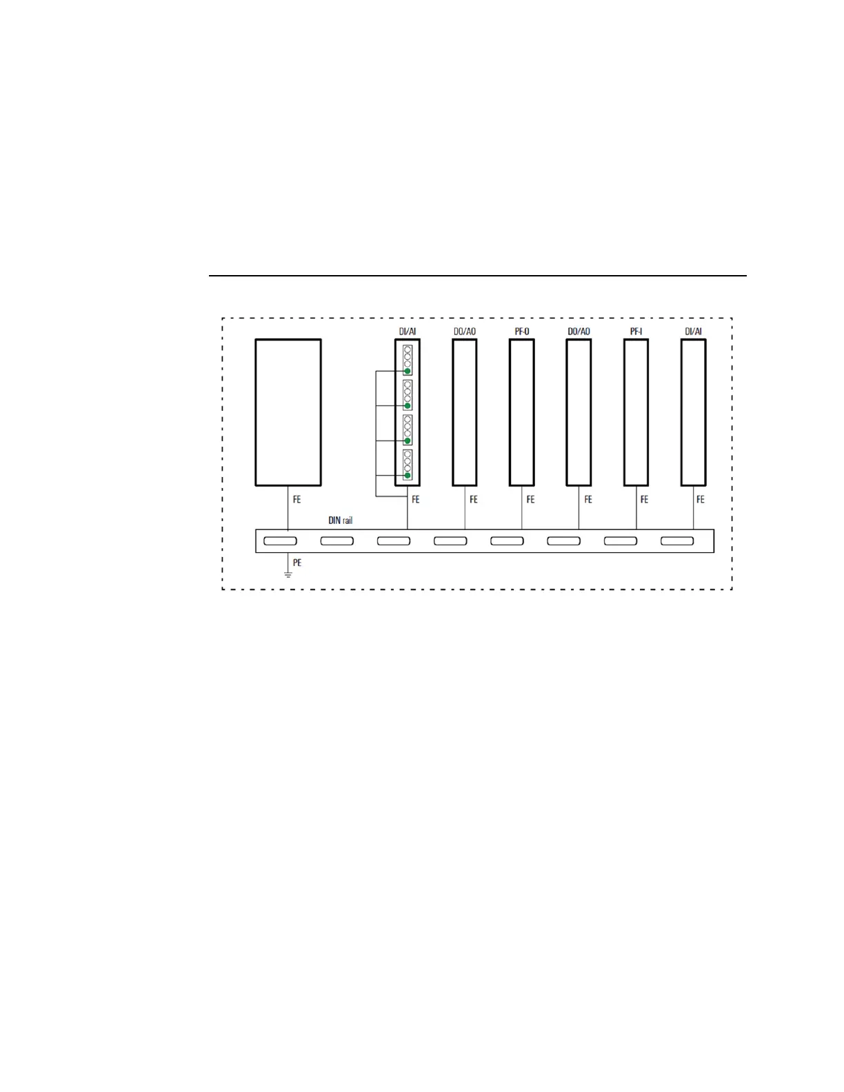
7.2.3 Non-Isolated Design
In a non-isolated design, the reference potentials of control and load circuits are galvanically
connected to each other.
Figure 255: RSTi-EP Earthing Concept
The spring contacts underneath the module and the network adapter snap into the DIN rail
to make a connection.
7.3 Electromagnetic Compatibility (EMC)
RSTi-EP products completely meet EMC requirements. EMC planning, however, is necessary
prior to installation.
Aspects to consider include all potential interference sources such as galvanic, inductive and
capacitive couplings, as well as radiation couplings.
7.3.1 Ensuring EMC
To ensure EMC, the following basic principles must be observed during installation of the
RSTi-EP modules:
•
Proper, extensive earthing of inactive metal parts
•
Correct shielding of cables and equipment
•
Proper layout of wires – cabling
•
Creation of a uniform reference potential and earthing of all electrical equipment

 Loading...


