User Manual Section 5
GFK-2958L May 2021
Detailed Description of I/O Modules 235
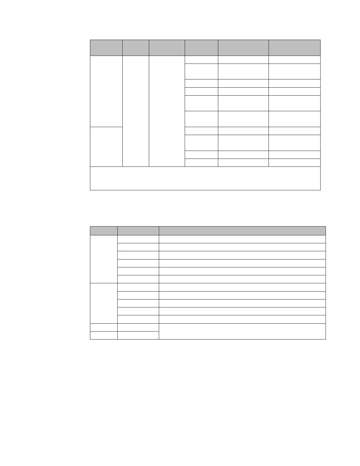
loads set value into
counter value
Counter 1: status
bits 11.1 - 11.5
Deactivate
comparison bit
†
Internal process data mapping with data format “Standard”. Depending on the fieldbus
specification and the data format of the communicating fieldbus components the bytes and/or
words can be reversed during data transfer.
5.17.7 Process Alarms for EP 5112
Counter 0: Overflow, underflow, or end value reached
Counter 0: Comparison value reached
Counter 1: Overflow, underflow, or end value reached
Counter 1: Comparison value reached.
Status Counter 0: Input Channel 0 A (Track A)
Status Counter 0: Input Channel 0 B (Track B)
Status Counter 1: Input Channel 0 A (Track A)
Status Counter 1: Input Channel 0 B (Track B)
16 But Time Stamp 0 … 65535µs, rotating
5.17.8 Setting Up the Counter
To start a counting process at least the signal mode needs to be parameterized and a rising
edge at the bit QX8.2 or QX10.2 respectively (Set SW gate) of the control word is required.
You can define the counter functions by parameterizing: the counting mode, a primary
direction (counting up/down), and the counting behavior. In addition, you can
parameterize options for setting a comparison bit (conditions, hysteresis) as well as
producing a process alarm (refer to Section, Additional Counter Features).

 Loading...


