User Manual Section 5
GFK-2958L May 2021
Detailed Description of I/O Modules 181
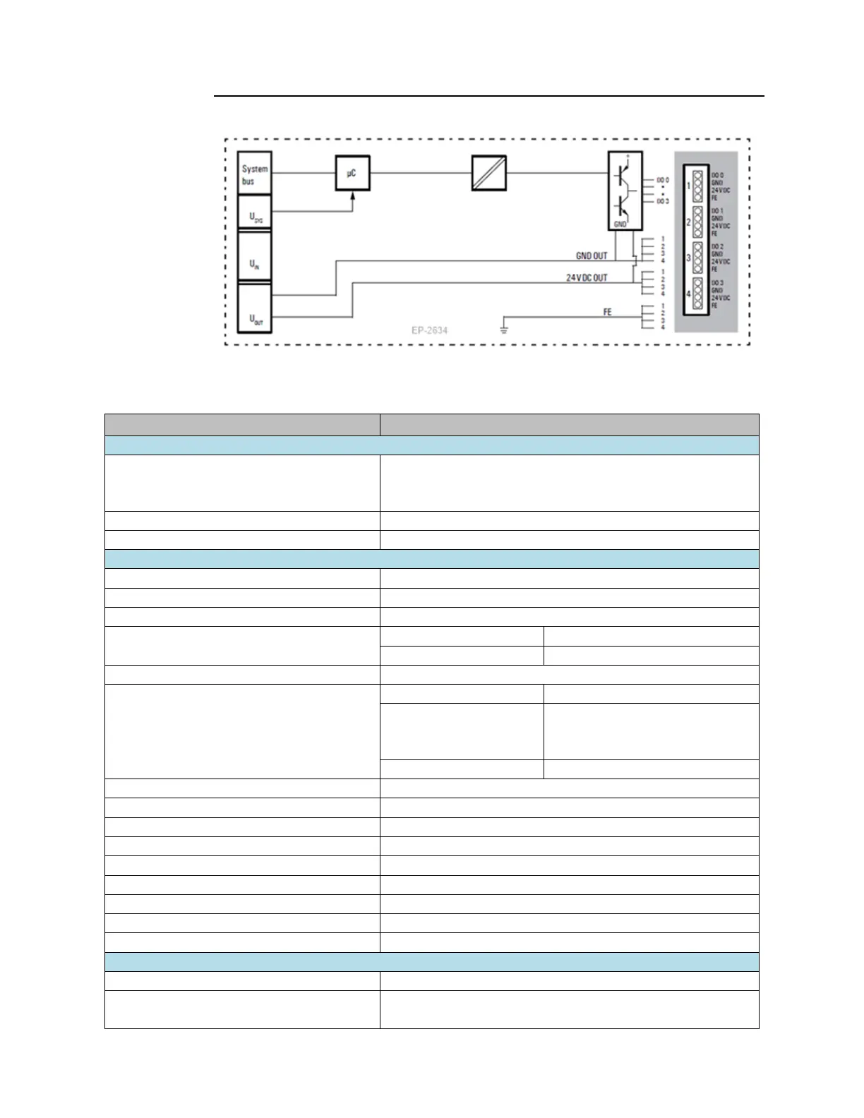
Figure 89: Block Diagram EP-2634
5.10.2 Specifications EP-2634
Process, parameter and diagnostic data depend on the network
adapter used (refer to Section 3.1, Order and Arrangement of
Modules).
RSTi-EP I/O communication bus
ohmic, inductive, lamp load
low » high max. 100
μ
s; high » low max. 250
μ
s
Breaking energy (inductive)
Resistive load (min. 47Ω)
0.2 Hz without free-wheeling diode
1 kHz with suitable free-wheeling
diode
2-wire, 3-wire, 3-wire + FE
max. 2 A per plug, total max. 8 A
Constant current with thermal switch-off and automatic restart
Response time of the current limiting circuit
Individual channel diagnosis
Current consumption from system current path
ISYS

 Loading...


